Toyota 4Runner 1996-2002: How to Disable VSC and Traction Control
Learn what you can do to have more control over your 4Runner's VSC and TRAC systems. If you want to disable these features, you have come to the right place.
This article applies to the Toyota 4Runner (1996-2002).
The 2001 and 2002 4Runners were built with safety in mind when the manufacturer decided that skid and traction control were needed. While these functions certainly do increase the safety features of the truck, they can also have some very bad side effects. In essence, the VSC allows the 4Runner to take over control when it senses a sideways skid while cornering or turning on a curve. When this happens, your 4Runner will take over braking and apply braking to each of the four wheels. It will also take over the engine (or your gas pedal) and cut power to the engine itself. It can also sense an under-steer or an over-steer condition and take over steering as well, until the vehicle gets back under control.
While this can certainly save your life someday, it also has the potential of doing great harm when for valid reasons, you have to pull out into heavy traffic and you mash the gas while making your turn and need to greatly get up to speed. The vehicle can be fooled into thinking you are in a skid and will cut engine power when you need it most. The TRC or traction control functions in a similar fashion, cutting power when it detects wheel spin. Again, when you really need such power and this function kicks in, it can be detrimental rather than helpful. There are many 4Runner owners who have figured out how to disable these features as needed. If this is something that interests you, learn how to do this mod yourself in your own garage. You will save lots of money from having a pro do this job for you and you likely cannot have it done at a dealership. If you are not electrically inclined at all, you may wish to find someone you trust who really knows the 4Runner and shell out the money, because you can easily compromise your computer system and that will end up costing you a great deal more.

Materials Needed
- 22AWG wire
- Soldering iron and solder
- Wire snips
- Electrical tape
- Shrink wrap (optional)
- Four (4) 12 volt DC SPDT relays
- Toggle Switch
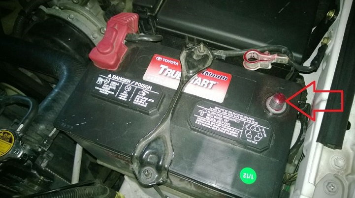
Step 1 – Disconnect your battery
You'll be working on some electrical components that are directly connected to your vehicle's computers. You want to make sure that you have disconnected the power first before proceeding.
- Pop the hood.
- Disconnect the negative (black) battery terminal first.
- Disconnect the positive (red) battery terminal next.
Step 2 – Find the VSC ECU
The skid control ECU is under the dash near the driver's kick plate panel. You'll need to see behind this box for the pin holes and numbers. You will be looking for the following pins:
- V18-3 (red wire with black tracer)
- V18-8 (black wire with blue tracer)
- V18-24 (pink wire with green tracer)
If the coloring or number schema doesn't match up on your vehicle, you may want to have a professional do this job for you. You can do a lot more bad than good messing these connections up.
- You will install three of your relays near this VSC ECU.
- You will mount and install the toggle switch where your fog lamp switch would be, as you should have a spot reserved for it already.
- Mount the toggle switch to the fog light bay and make four 12V wire connections. Use plenty of wire to meet the VDC ECU (three of the wires) and one longer wire to meet the ECM behind the glove box.
- Connect a 12v wire to each of the coils inside the relay. Be consistent with which coil you wire to, and do that same one for each relay.
- Connect two ground wires to each relay: one on the other coil (opposite side you just wired) as well as the NORMALLY OPEN post on the relay.
- Perform the rest of these steps one relay at a time, so you do not cross connect anything.
- Take the V18-3 (red and black) wire about an inch or two from the ECM and snip it in half. Splice in (soldering works well here) a length of 12v wires (two of them) on each of the cut pieces so they reach back to your relays. Take the spliced wire that is coming from the ECU end and connect it to the common post in the relay. Take the spliced wire that is coming from the harness end and connect it to the NORMALLY CLOSED post in the relay. You may also wish to use shrink wrap over the soldered or spliced areas to ensure they do not come apart.
- Take the V18-8 (black and blue) wire and repeat the same process.
- Take the V18-24 (pink and green) wire and repeat the same process.
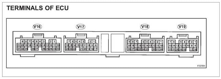
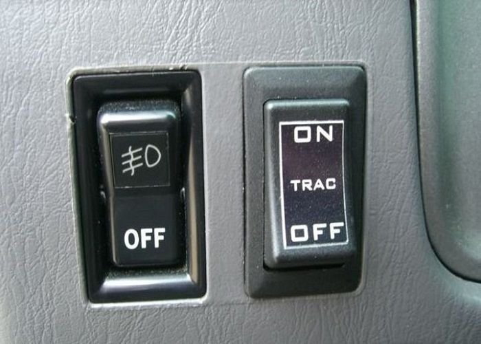
Figure 3. Mount and install your new toggle switch to the existing fog lamp toggle area for a nice clean look. 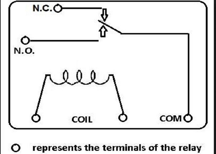
Figure 4. Typical single pole, double throw relay wiring diagram.
Step 3 – Locate your ECM
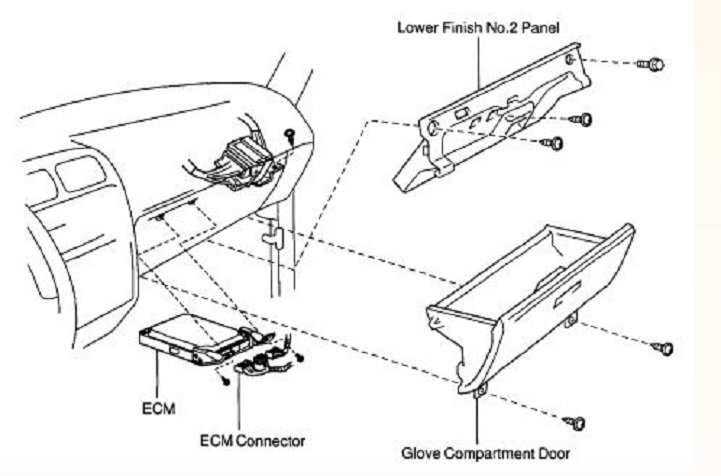
Your ECM is behind the glove box. It is not too bad to get to; you just need to remove the glove box first.
- Remove the contents of your glove box.
- There are two screws on the bottom side of the glove box. Remove these two screws and the glove box will come right out.
- Remove the glove box rear panel by removing the three bolts that hold this in place.
- Once the ECM is located, you'll work with the black connector, second from right.
- Follow the same process with the ECM as you did with the VSC connections.
- Run the 12v from the toggle to the relay, which will be near the ECM, so this wire is much longer.
- Make the connections to the relay poles.
- Splice the wires from the ECM to the relay.
- Reinstall the back panel and the glove box.
Step 4 – Test your connections
If you have a place to safely do so, test your TRAC and VSC by spinning your wheels and sliding your rear end.
Related Discussions
- Disabling VSC and TRAC on 2001 4Runner - YotaTech.com
- AndyMod 2.0 ABS Active - YotaTech.com
- New Improved Andy Mod - YotaTech.com
- TRAC Off, VSC TRAC, ABS Lights On - YotaTech.com
- 01-02 How to Zero Point Calibrate VSC System - YotaTech.com

