
ChefYota4x4's 1987 4Runner Build-Up Thread
 09-12-2013, 09:28 AM
#7701
Glad to hear you got things worked out with the government on your moms issue. I like how they do that, lets just go back umpteen years and see if they can prove this or that. grrr.
As far as Helto and that truck, I would rather see someone over pay for a great truck then get a smoking deal on one that they have to send to the shop. That smoking deal can get expensive quick. I seen he spent $1300 for a repair. Ouch!!! There is an 86 SR5 extra cab in the works for me to be working on for a friend. Will be a few months, as I have a few things to wrap up.
With all of the new parts you have stuck in, it is suprising you still have your gremlin. Once you get it figured out, you know your runner is about as new as you can get it. So there is some good news out of all of this.
I have been out of town so getting caught up on what is going on. You are always getting something done. Makes me realize I need to get off of my rear.
Yeah, the gremlin remaining situation?.... I won't lie, ....that bummed me out a little bit... But after all this crap? I really wasn't that surprised. I just moved right on to the next thing in life that day. However, I haven't really extensively tested it since I put all those in. I just burped it the best I could, drove around a bit and then had to get home and garage it........ Its been there ever since, because I have been taking my mom all over the place in the Honda.... I think part of that is that I am just reading fighting, possibly, even more problems now? I think it's more likely that they are just different. If that's the case then that clearly means that something else is affected bye these sensors and is unhappy and showing it. Fuel pump? Air flow meter? I have no idea... I will do a start and pause video, mentioning the Toyota Service Bulletin and parts and process I took that is required, and let it show exactly what it's doing now. What I don't like is that it's a ling even lower , even when fully warmed up. The reason I don't like that is that it means I might have to take that screw up again even more, which is not normal.
Last edited by ChefYota4x4; 09-12-2013 at 09:31 AM.
 09-12-2013, 03:02 PM
#7702
I think I got it!.......
I might have a very high and tight way to mount my OBA.....
I have been looking to other threads/posted examples as to where to mount/or store & carry-on-portable/ my OBA......
Upon getting under my rig, I realized that I am pretty limited as to where I can hard mount a compressor and tank...... BUT, I had been looking at things, in regards to me hard mounting a tank and compressor in the spare tire carrier location, in a front to back method as far as the tank. However, if I just drop the tire stops off of that frame bracket around 3 inches, I can actually use the portions of the tire stops that protrude from the cross portion of the frame as brackets to secure the tank left to right, just behind the frame crossmember, and the same for the compressor on the opposite side of the same frame crossmember that goes left to right. It should be fairly easy to put spacers between the spare tire stops and that cross member .
The space between the lowest portion of the corrugated bed and the highest portion of the tire stop pieces on either side is 5.5". The tank is only 7 inches tall, and including the corrugated part..... Since the ports are mounted on what will be the ends & side & bottom.... I can get as close as I can to the corrugated underside of the bed.
I can then run roses two other side, lol, to air ports. To the sides and through the pinch welds at the bottom of the body next to the sliders. That way I can have a port on either side and just run around with the air hose after a quick disconnect from the port lol. They make covers for those ports but I saw a guy using a heavy duty balloon as a cover and that is pretty darn good idea. Just keep dirt and crap out of there.
I am leaning towards the AZOB2K1A kit..... But I can only find it available on Air Zenith's site......
http://shop.air-zenith.com/dual-ob2basickit-1-1.aspx .....
There are plenty of authorized reseller sites that sell all of these parts but they're always separate or with two compressors. There is actually a great deal with two compressors for only $210 more than this one....
........ For example, regarding the authorized resellers, here's one from a company that most people know called AutoAnything.com.....
http://item.mobileweb.ebay.com/viewi...d=181208236898
Another ebay item sale from the same company, without the digital gauge, is exactly the same price. The digital gauge by itself is $71......
Not sure if I can find the kit without the things I don't need like that digital gauge. But sometimes it seems like you're just throwing it in. The compressors by themselves or a minimum of $340 at the cheapest, And that doesn't include tax. However, if you order it directly from Air Zenith's site, there is a $10 shipping but no tax. I guess you could say in California that kinda balances out because the tax would be around $50. Meh! Lol.....
Thanks for your input guys, Toyota, especially, got me thinking about how alligator clips can be somewhat inadequate with a electrical items to put out so much power and draws so much amperage.
The ARB TWIN is the other choice, but I would then need to add at least A pressure switch and gage and other things in order to basically have the same type of setup. I believe from everything I've read the ARB should be a little faster, but I don't know that it's better. Both of them have remote filter setups that come with the compressor. So, I'm just going to put everything down on two different lists and look a little more into things as far as speed and reliability, and then I will have my setup ready to order. One good thing about the ARB is that it is only 4 inches tall, so I can mount it in that spare tire location and probably just run that by itself and be okay. But, having the tank could be very convenient if I did ever run into the need to have an air tool on board for longer expedition style trips like a couple that I have been trying to plan .
I'm almost there guys, just looking at a couple more things.
Here are some pictures of the techs I'm talking about. They are 28 inches long and 7 inches tall...
Steel....


Aluminum....


Both of those are made by AZ.....
Here is the procedure for setting up the kit with one compressor.....

I might have a very high and tight way to mount my OBA.....
I have been looking to other threads/posted examples as to where to mount/or store & carry-on-portable/ my OBA......
Upon getting under my rig, I realized that I am pretty limited as to where I can hard mount a compressor and tank...... BUT, I had been looking at things, in regards to me hard mounting a tank and compressor in the spare tire carrier location, in a front to back method as far as the tank. However, if I just drop the tire stops off of that frame bracket around 3 inches, I can actually use the portions of the tire stops that protrude from the cross portion of the frame as brackets to secure the tank left to right, just behind the frame crossmember, and the same for the compressor on the opposite side of the same frame crossmember that goes left to right. It should be fairly easy to put spacers between the spare tire stops and that cross member .
The space between the lowest portion of the corrugated bed and the highest portion of the tire stop pieces on either side is 5.5". The tank is only 7 inches tall, and including the corrugated part..... Since the ports are mounted on what will be the ends & side & bottom.... I can get as close as I can to the corrugated underside of the bed.
I can then run roses two other side, lol, to air ports. To the sides and through the pinch welds at the bottom of the body next to the sliders. That way I can have a port on either side and just run around with the air hose after a quick disconnect from the port lol. They make covers for those ports but I saw a guy using a heavy duty balloon as a cover and that is pretty darn good idea. Just keep dirt and crap out of there.
I am leaning towards the AZOB2K1A kit..... But I can only find it available on Air Zenith's site......
http://shop.air-zenith.com/dual-ob2basickit-1-1.aspx .....
There are plenty of authorized reseller sites that sell all of these parts but they're always separate or with two compressors. There is actually a great deal with two compressors for only $210 more than this one....
........ For example, regarding the authorized resellers, here's one from a company that most people know called AutoAnything.com.....
http://item.mobileweb.ebay.com/viewi...d=181208236898
Another ebay item sale from the same company, without the digital gauge, is exactly the same price. The digital gauge by itself is $71......
Not sure if I can find the kit without the things I don't need like that digital gauge. But sometimes it seems like you're just throwing it in. The compressors by themselves or a minimum of $340 at the cheapest, And that doesn't include tax. However, if you order it directly from Air Zenith's site, there is a $10 shipping but no tax. I guess you could say in California that kinda balances out because the tax would be around $50. Meh! Lol.....
Thanks for your input guys, Toyota, especially, got me thinking about how alligator clips can be somewhat inadequate with a electrical items to put out so much power and draws so much amperage.
The ARB TWIN is the other choice, but I would then need to add at least A pressure switch and gage and other things in order to basically have the same type of setup. I believe from everything I've read the ARB should be a little faster, but I don't know that it's better. Both of them have remote filter setups that come with the compressor. So, I'm just going to put everything down on two different lists and look a little more into things as far as speed and reliability, and then I will have my setup ready to order. One good thing about the ARB is that it is only 4 inches tall, so I can mount it in that spare tire location and probably just run that by itself and be okay. But, having the tank could be very convenient if I did ever run into the need to have an air tool on board for longer expedition style trips like a couple that I have been trying to plan .
I'm almost there guys, just looking at a couple more things.
Here are some pictures of the techs I'm talking about. They are 28 inches long and 7 inches tall...
Steel....
Aluminum....
Both of those are made by AZ.....
Here is the procedure for setting up the kit with one compressor.....
Last edited by ChefYota4x4; 09-12-2013 at 03:32 PM.
09-12-2013, 05:37 PM
#7705
i have 32 inch tires. but i have a set of 35 mounted on some 15x10 rims i can test my compressor on to if you really need fill up times. but i see your have already narrowed it down to the other two. either way me know if you need me to do a test or not.
09-13-2013, 08:15 AM
#7707
Super Moderator
Staff
iTrader: (1)
Join Date: Aug 2008
Location: Anderson Missouri
Posts: 11,788
Likes: 0
Received 25 Likes
on
22 Posts
Looks like you got alot of planning involved in your onboard air. Something I dont know a whole lot about but will someday. Atleast you didnt get 15 pages ahead of me and I play catch up to where you are.lol
09-13-2013, 08:28 AM
#7708
You can add a tank to any compressor. with a standalone compressors, you will need to buy a pressure switch. Relay. Tank. Switches and what not. It's not hard to do but I do wiring all the time.
09-13-2013, 11:48 AM
#7709
Yeah, I can't hardly decide from a choice of two, let alone 3! Hehe. ... No, but really? ? ?..... I just couldn't seem to find the Puma without the tank attached( what I mean is, I can't seem to find it for sale by itself).... And if I'm going to hard mount a tank......I think I should go at least 5 gallons. It may very well be easy to detach the handle and compressor, without a problem. But, even at the better price, I would still be left with a smaller tank I wouldn't really need. Does that make sense? The funny thing is that they sell the tank with a gauge & the fittings and all that ready to go, but I can't seem to find the compressor by itself. It is a pretty bad arse compressor, and I like the reviews I read... I think the AZ OB2 might just have a lil bit extra pop?(And yet I am not positive, because the AZ seems to have around 4.25CFM at ZERO-PSI/FULL FLOW and up to 30 PSI..... But then has around 2.25 cfm at 90 psi.... And the Puma has 3.4 cfm at 30 psi and 3.0 CFM at 90 psi... Is that because the AZ is a 200 psi compressor? Does it drop off a little sooner because it has a wider range? I'm just not sure how that works.) I definitely think the Puma, as a single compressor, is a little more effective, at least, than the Viair 480C. The only problem I see is that that kit that the Puma comes with, even if I pull off all the hardware that the kit comes with, like the pressure switch and everything else, is it all standard fittings? Or is it made to fit and mount the hardware to the Puma tanks and set up... It seems to have hard lines on there.... has to be low-profile to mount under there in the spare tire location.
********************
That brings me to something that I wanted to share. I did find a site with whom I have a prior discount set up that immediately reminded me, popping up in notification to check in my cart for the price... I found a kit, the exact same kit, with the aluminum 5 gallon tank and digital gauge and pressure switch and two AZ-OB2 compressors for under $700 shipped. That's only $150 more then the same kit with one compressor.... The reason I bring that up is because these AZ-OB2 compressors are $350 dollars each. I just don't have the time to figure out who wants one of these for a very reasonable price and so forth... or I would just do that, shipping off one of the compressors for someone else. I could just run two, but the reason I'm apprehensive of running two of those is because it would draw around 70 amps max. With my 130 amp alternator installed & a good battery, I think I could be okay with that, so I thought I would ask that as well, what you thought? '70AMPS TOO MUCH?' ( it would basically run a little over 7CFM at wide open throttle, 0 psi ... Probably could fill the 35 from 15 pounds to 35 pounds in under a minute. The ARB twin is really nice at 6.38 CFM at wide open throttle, 0 psi....... But it's also around $500 at the cheapest, with no installable gauge and I'm not sure but i think itis with no pressure switch, which would have to be mounted on a tank that I would also have to buy separately. I think if I wanted to add a five gallon tank to that ARB twin, it would wind up in the $800 area. Then again, it would just be one unit and not 2! Lol.....
Last edited by ChefYota4x4; 09-13-2013 at 04:33 PM.
09-13-2013, 10:34 PM
#7710
The puma can be taken apart. A lot I guys have done it and move the tank else where. Te fittings are all standard and u wouldn't have any issue finding fittings for it. The hard line is there because the tank and compressor doesn't flex apart from each other so why use a rubber hose. Plus hard pipes will last longer.
The think the puma compressor alone is bigger than any other 12v compressor I have seen. It's just a tad smaller than a small car ac compressor. The size alone maybe why the puma puts out more cfm at rated psi u mention.
Don't know to much about weather you alternator will handle the extra 70amps
I know factory amps put out max of like 30amps at idle with no load. I know some of you guys say your disappointed with high output amps only supplying similar amp at idle. You have to understand that no load at idle it will only put put enought to keep the battery at x amount voltage (basically enough to keep battery charged) when you put a load on it. It can push out more amps and well into 100 plus amps. So I guess as long as your wiring is correct. It shouldn't be a problem. I just don't know if it is safe to have it push 100amps at 5 plus minutes at a time. I say 100 is a little high but if your at night with headlights on (10-30amp) plus compressors (70amp). U can see it can be 100 amp load at one time. I'm not expert at alternators so I could be wrong and having it push 70 plus amps at idle for c amount of time is ok
09-14-2013, 01:03 AM
#7711
Super Moderator
Staff
iTrader: (1)
Join Date: Aug 2008
Location: Anderson Missouri
Posts: 11,788
Likes: 0
Received 25 Likes
on
22 Posts
I would look into some serious wiring upgrade. Like Toyo mentioned 100 amps for 5 minutes would scare me, but I am not sure what all would need upgraded. Luckily you have RAD in your area and he would have a ton of information as what would be the best way to go for electricity. Just something I am uncomfortable with when it comes to electricity. I have an understanding of the verrry basics.
09-14-2013, 09:57 PM
#7712
How To Wire Upgraded Alternator
Hi Mark and guys,
In earlier discussion on Phil's thread, we agreed to simply upgrade alt-to-batt wire ("B"), and keep it in stock location.
However, in an extreme application like this one (Mark's 70-amp compressor, and winch), I think the circuit below would be safer and handle more worst-case scenarios:

Note: In stock circuit, S (thin white sense wire) taps off the B (Thick white) wire right before the fuse block.
Circuit Above:
Possible Worst-Case Scenarios (WCS):
To Illustrate Worst Case Scenario 1: Battery goes out/Disconnected while engine on, stock and and auxiliary circuits on:

Alternator will handle combined stock and auxiliary currents.
To Illustrate Worst Case Scenario 2 OR 3: Alternator goes out or gets disconnected, or engine is off (hence alt also off) while accessories, stock and auxiliary circuits are on and Bob Seger playing loud :
:

Battery will handle combined currents without overloading main FL (80-amp)
In earlier discussion on Phil's thread, we agreed to simply upgrade alt-to-batt wire ("B"), and keep it in stock location.
However, in an extreme application like this one (Mark's 70-amp compressor, and winch), I think the circuit below would be safer and handle more worst-case scenarios:
Note: In stock circuit, S (thin white sense wire) taps off the B (Thick white) wire right before the fuse block.
Circuit Above:
- Disconnects stock (B) wire. (Insulate terminals, roll-up and secure for ease of restoring to stock.)
- Connects alt directly to battery with upgraded wire and fuse to handle alternator capacity.
- Bypasses stock fuse and FL network, and protects new wiring with appropriate fuse.
Possible Worst-Case Scenarios (WCS):
- Battery dies or gets disconnected while engine and auxiliary circuits are on,
- Alternator dies or gets disconnected while engine and auxiliary circuits are on, and
- Auxiliary circuits, stock lights and AC on, and Bob Seger playing loud, while engine (hence alt off) off.
To Illustrate Worst Case Scenario 1: Battery goes out/Disconnected while engine on, stock and and auxiliary circuits on:
Alternator will handle combined stock and auxiliary currents.
To Illustrate Worst Case Scenario 2 OR 3: Alternator goes out or gets disconnected, or engine is off (hence alt also off) while accessories, stock and auxiliary circuits are on and Bob Seger playing loud
:Battery will handle combined currents without overloading main FL (80-amp)
Last edited by RAD4Runner; 11-09-2013 at 11:37 PM. Reason: updated schematic
09-14-2013, 10:56 PM
#7713
RAD,...... ur Rad! Lol...
Seriously, you're a solid dude, and I'm very appreciative for the help. Are u saying the best method would be to run a fat wire to battery AND tap in and run fatter wire to FL network? I see one or two of the diagrams is pointing to the aux fuse block?.... that is only allowing 30Amps per circuit/up to 150 amps max aat any time (but only 30A Max-per, of 12)
I will want to get the most of this new 130A alternator and soon to be DIE HARD AMG Battery.... But, I don't wanna "push" things, if that's gonna be the case with two 35Amp-draw compressors.... So, maybe just sticking with the AZOB2KA1 kit instead of KA2.... along with all the lights that are coming soon, my amp u mentioned, and Aux power, inverters at times.....
I have to look at these pics from a PC, print them out, etc. I'm getting the diagrams better, I'm just still a lil unsure of the charging system wiring routing. Need to look over Phils stuff as well.
Thanks again for always being such a big help to us that I have to do well in the realm of the electronically inept! Haha. Jk, I'm getting it, but YOU GOT IT,.....and I appreciate "IT"! Hehe
.......Mmmmmkayyyy, saved all the pics and sent them to puter via wifi! Much better!.... hmmmmm.... ingesting. So what do you think I.... Let me rephrase that... What would you do, Ray? Lol
Last edited by ChefYota4x4; 09-14-2013 at 11:05 PM.
09-14-2013, 11:43 PM
#7714
Mark, no need to change stock FL.
Re fuse block use existing distribution block for lights and other light-duty stuff.
Connect compressor directly to battery through 70-amp fuse as in vendor picture.
Connect winch directly to battery through its own switch/relay setup.
Re fuse block use existing distribution block for lights and other light-duty stuff.
Connect compressor directly to battery through 70-amp fuse as in vendor picture.
Connect winch directly to battery through its own switch/relay setup.
RAD,...... ur Rad! Lol...
Seriously, you're a solid dude, and I'm very appreciative for the help. Are u saying the best method would be to run a fat wire to battery AND tap in and run fatter wire to FL network? I see one or two of the diagrams is pointing to the aux fuse block?.... that is only allowing 30Amps per circuit/up to 150 amps max aat any time (but only 30A Max-per, of 12)
I will want to get the most of this new 130A alternator and soon to be DIE HARD AMG Battery.... But, I don't wanna "push" things, if that's gonna be the case with two 35Amp-draw compressors.... So, maybe just sticking with the AZOB2KA1 kit instead of KA2.... along with all the lights that are coming soon, my amp u mentioned, and Aux power, inverters at times.....
I have to look at these pics from a PC, print them out, etc. I'm getting the diagrams better, I'm just still a lil unsure of the charging system wiring routing. Need to look over Phils stuff as well.
Thanks again for always being such a big help to us that I have to do well in the realm of the electronically inept! Haha. Jk, I'm getting it, but YOU GOT IT,.....and I appreciate "IT"! Hehe
.......Mmmmmkayyyy, saved all the pics and sent them to puter via wifi! Much better!.... hmmmmm.... ingesting. So what do you think I.... Let me rephrase that... What would you do, Ray? Lol
Seriously, you're a solid dude, and I'm very appreciative for the help. Are u saying the best method would be to run a fat wire to battery AND tap in and run fatter wire to FL network? I see one or two of the diagrams is pointing to the aux fuse block?.... that is only allowing 30Amps per circuit/up to 150 amps max aat any time (but only 30A Max-per, of 12)
I will want to get the most of this new 130A alternator and soon to be DIE HARD AMG Battery.... But, I don't wanna "push" things, if that's gonna be the case with two 35Amp-draw compressors.... So, maybe just sticking with the AZOB2KA1 kit instead of KA2.... along with all the lights that are coming soon, my amp u mentioned, and Aux power, inverters at times.....
I have to look at these pics from a PC, print them out, etc. I'm getting the diagrams better, I'm just still a lil unsure of the charging system wiring routing. Need to look over Phils stuff as well.
Thanks again for always being such a big help to us that I have to do well in the realm of the electronically inept! Haha. Jk, I'm getting it, but YOU GOT IT,.....and I appreciate "IT"! Hehe
.......Mmmmmkayyyy, saved all the pics and sent them to puter via wifi! Much better!.... hmmmmm.... ingesting. So what do you think I.... Let me rephrase that... What would you do, Ray? Lol

 09-15-2013, 06:40 PM
#7716
MArk,
No need to change main FL. Just wire as in first schematic above. Other schematics are just to illustrate current flow during worst-case scenarios.
No need to change main FL. Just wire as in first schematic above. Other schematics are just to illustrate current flow during worst-case scenarios.
09-15-2013, 11:47 PM
#7717
Gotcha, RAD! ....
I should have a cool update in the next couple days, but I'm also trying to work out a way to get to Pismo for Jamboree. Really wanna go...
Thanx to Toyo & many others, I think I finally have a way to hard mount the compressor, upright, in a safe location, under the rig.....
I ordered the AZOB2KA1 kit,......
http://shop.air-zenith.com/dual-ob2basickit-1-1.aspx
Along with a air filter relocation kit...
http://shop.air-zenith.com/ob2airfil...cationkit.aspx
I might be adding this bracket, but first I need to see if I can pull it off of what I have. I actually have a really good idea on how to mount the compressor to the cross tube where the fuel tank is held up from, using D-Bolts... I might use a bracket it depends... But the compressor itself has an integrated mounting bracket that can go three different ways... If not, I will be likely grabbing a bracket like this and welding it to the cross tube.....
http://www.viaircorp.com/OnRoad/Part...ngbracket.html
Absolutely freaking ecstatic to be done making a decision. I'm glad that I took my time because I really did need to look into this a lot. Every single location, darn near everyone, seems to have a problem in the case of my truck for some reason or another. For one the location of my LPSV, the location of my rerouted exhaust, the fuel tank on one portion of the frame rail that I could have used, the exhaust on the other side,... Its just one of those things, you really need to take off super good look at where you're going to put this and make sure that you can fit a compressor this size wherever it is that you were planning.
I will do a post with they short video demonstrating what I plan to do, ASAP. However, I have a big day tomorrow and I will likely not be back until around 3 or 4, so I will try to pop one out then.
Sorry to take so long, but I really needed to find something that will work for me and also work as long as possible. This is as much weight and space as I wanted to take up for now..... It will be nice to have that digital gauge and 165-200 psi pressure switch, along with 5 gallons of air ready to go at the end of the day. I can switch it on and charge that up and be ready to go and by the time the compressor kicks on it will have had plenty of time to cool off. Not that it's absolutely necessary but it will help with longevity I think. Should be able to easily relocate the filter into the side panel...
Looking forward to this!
*************************************
While I'm waiting on the OBA KIT, I want to install the new tome 130Amp alternator, Headlight Harness upgrade, and look into a couple more gremlin suspects.....
I might have mentioned it,....but my gremlin is still there and even worse in some ways. I won't go into it other than to say its idling down every time upon going into closed loop and the same thing with the hot restarts. On top of that, the RPM's drop off when I turn on the headlights again. Some really funky crap, guys.
09-16-2013, 01:28 PM
#7718
Hey Rad, anyone......
I'm planning to grab the large fuse and possibly a multi-port positive terminal (I have a solid wing nut style, but I think a HD multi-port terminal would be cleaner/more effective).
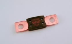
Does this fuse look sufficient?......
150 Maxifuse......

http://m.oreillyauto.com/mt/www.orei...d=150+amp+fuse
*Just making sure:
1. Rad, you suggest leaving the battery positive terminal to 80A fusible link wire alone? Just add fused wire to battery + terminal, directly from ring post on alternator?
2. Do I leave the existing ring terminal wire thqt is attached to the alternator now, after replacing the post ring with a larger one? (Existing ring connector is too small for the modified 3 wire stator/Alternator stud)....Or remove it, cut and wtap it well, then tuck away for "Just in case" stuff? Haha.
******************************************
AZ OB2 Compressor Mounting Ponderance...... and likely mounting location.....
* [Again, thanks to everyone for taking so much time and care in explaining things and relaying their thoughts and hypothetical layouts with me. Toyo, I will just let you speak for yourself, I'm curious if you agree, that when you looked all the pictures and videos I sent you, this is a little bit of a tight spot/unlimited choices - type of situation..... in regards to mounting everything underneath, while still keeping the compressor up right and as far as possible from heat....? ] *
* While looking over possible locations for mounting a 12"L x 5.5"W x 8.11"H Air Zenith OB2 Compressor, I quickly realized that not only did I need to plan tgis out well, but I also sae that in most places if like to put it, I either had to put the compressor very close to the exhaust or the heat from the compressor woyld be less than ideal for said other areas...
The first idea was to mount either mount compressors or tank on the rear side of the spare tire/structural crossmember in the rear-underbody......

The picture above shows that with the tank there a, I would be pushing it due to the fact that the tank is much wider and cannot be pushed towards the rear of the bumper/ above the bumper without protruding into an area that could put it more at risk for coming down on it when trying to clear a rock or other of circle of road... I don't know like a tree stump? Hahaha. This location would put the compressor just clearing the top of the hitch portion. However, as the compressor travels from the center towards the side, the cross support to the bumper and grill up word toward the rear quarter panels... Just really limits my space and pushes the compressor literally right up within a half an inch of the bottom portion of the corrugated bed underside.
Another few spots that I felt were either too hot or wouldn't offer adequate protection. ...
( after removing the torsion bar bracket of course )....

This may still be viable but I would need for stair in there to keep it cool, because while the insulation might be protected from the heat on the outside, coming in, it will also insulate the heat within the panel... I would have to remove the jack and maybe relocate the washer bag... Maybe just modify the jack bracket. I'm not sure it will fit with that bracket in there though to be honest....

This might be a super fantastic location, but my LPSV is there, and on top of that, it is pretty close to the tire which would be shooting pool of water and mud up in that area under certain circumstances... I could easily build a shield and I may still depending on where I put it.... But, I think it would be a bit difficult to keep it from getting slathered in this location? Hehe.

Another location outside of the cargo access door, opposite the other side where my high lift jack is. Obviously it would not be too in the way... And I could even mount it right to the cargo access panel door that locks. This is only if it doesn't fit inside, but I do think it would be ventilated a lot better. I'm just not sure I would enjoy the heat that generates being inside of my cab....


Here are a couple mounting locations that were sent to me by Toyo......
The first picture, notice the lack of an LPS be and the different location for mounting the shock.....

This mountain location is great, but it appears different than mine in that I only have one cross member in the rear. Maybe this is for a 2nd gen or something? Also, the size of my compressor will not allow me too mount the compressor head inside of the structural portion of the crossmember... There's just no room.....( however, I could mount them on other side of the crossmember right up against it, just simply would have to notch the crossmember slightly or build a bracket to enable me to mount it there... However, this puts it around directly in the middle between the rear bumper on the axle which is quite the wide open area and not really tucked up against something to protect it).....

Definitely something I wouldn't do, just because that is where I have my auxiliary fuse block and I guess because it's a little too much for him to the hood with the closed...

This will likely be my mountain location for the compressor, which I will either mount using the compressors intigrated mounting feet in a side mounting fashion, using u bolt D brackets or an actual mounting bracket welded to the pipe.... Or a plate mounted to the pipe using u-bolt D brackets and then mount the compressor to that plate.... The last probably being the most reasonable price next to just simply getting the Viair mounting bracket weldit up there. I will put the head thus far away from the exhaust possible, closer to the fuel tank........


^^^^^ this location will put the compressor between the axle in the fuel tank skid plate, pretty clear of anything ever fashion into it find some super odd Murphy law happenstance! Lol.
I will do a couple test fitting videos second the stuff arrived and I will also do my best to show my videos and pics just how to run the wiring for the alternator and the headlights wiring harness upgrade kit with ceramic connectors.
A picture of the kit I got and a couple videos demonstrating Air Zeniths Digital Gauge....

I'm planning to grab the large fuse and possibly a multi-port positive terminal (I have a solid wing nut style, but I think a HD multi-port terminal would be cleaner/more effective).
Does this fuse look sufficient?......
150 Maxifuse......
http://m.oreillyauto.com/mt/www.orei...d=150+amp+fuse
*Just making sure:
1. Rad, you suggest leaving the battery positive terminal to 80A fusible link wire alone? Just add fused wire to battery + terminal, directly from ring post on alternator?
2. Do I leave the existing ring terminal wire thqt is attached to the alternator now, after replacing the post ring with a larger one? (Existing ring connector is too small for the modified 3 wire stator/Alternator stud)....Or remove it, cut and wtap it well, then tuck away for "Just in case" stuff? Haha.
******************************************
AZ OB2 Compressor Mounting Ponderance...... and likely mounting location.....
* [Again, thanks to everyone for taking so much time and care in explaining things and relaying their thoughts and hypothetical layouts with me. Toyo, I will just let you speak for yourself, I'm curious if you agree, that when you looked all the pictures and videos I sent you, this is a little bit of a tight spot/unlimited choices - type of situation..... in regards to mounting everything underneath, while still keeping the compressor up right and as far as possible from heat....? ] *
* While looking over possible locations for mounting a 12"L x 5.5"W x 8.11"H Air Zenith OB2 Compressor, I quickly realized that not only did I need to plan tgis out well, but I also sae that in most places if like to put it, I either had to put the compressor very close to the exhaust or the heat from the compressor woyld be less than ideal for said other areas...
The first idea was to mount either mount compressors or tank on the rear side of the spare tire/structural crossmember in the rear-underbody......
The picture above shows that with the tank there a, I would be pushing it due to the fact that the tank is much wider and cannot be pushed towards the rear of the bumper/ above the bumper without protruding into an area that could put it more at risk for coming down on it when trying to clear a rock or other of circle of road... I don't know like a tree stump? Hahaha. This location would put the compressor just clearing the top of the hitch portion. However, as the compressor travels from the center towards the side, the cross support to the bumper and grill up word toward the rear quarter panels... Just really limits my space and pushes the compressor literally right up within a half an inch of the bottom portion of the corrugated bed underside.
Another few spots that I felt were either too hot or wouldn't offer adequate protection. ...
( after removing the torsion bar bracket of course )....
This may still be viable but I would need for stair in there to keep it cool, because while the insulation might be protected from the heat on the outside, coming in, it will also insulate the heat within the panel... I would have to remove the jack and maybe relocate the washer bag... Maybe just modify the jack bracket. I'm not sure it will fit with that bracket in there though to be honest....
This might be a super fantastic location, but my LPSV is there, and on top of that, it is pretty close to the tire which would be shooting pool of water and mud up in that area under certain circumstances... I could easily build a shield and I may still depending on where I put it.... But, I think it would be a bit difficult to keep it from getting slathered in this location? Hehe.
Another location outside of the cargo access door, opposite the other side where my high lift jack is. Obviously it would not be too in the way... And I could even mount it right to the cargo access panel door that locks. This is only if it doesn't fit inside, but I do think it would be ventilated a lot better. I'm just not sure I would enjoy the heat that generates being inside of my cab....
Here are a couple mounting locations that were sent to me by Toyo......
The first picture, notice the lack of an LPS be and the different location for mounting the shock.....
This mountain location is great, but it appears different than mine in that I only have one cross member in the rear. Maybe this is for a 2nd gen or something? Also, the size of my compressor will not allow me too mount the compressor head inside of the structural portion of the crossmember... There's just no room.....( however, I could mount them on other side of the crossmember right up against it, just simply would have to notch the crossmember slightly or build a bracket to enable me to mount it there... However, this puts it around directly in the middle between the rear bumper on the axle which is quite the wide open area and not really tucked up against something to protect it).....
Definitely something I wouldn't do, just because that is where I have my auxiliary fuse block and I guess because it's a little too much for him to the hood with the closed...
This will likely be my mountain location for the compressor, which I will either mount using the compressors intigrated mounting feet in a side mounting fashion, using u bolt D brackets or an actual mounting bracket welded to the pipe.... Or a plate mounted to the pipe using u-bolt D brackets and then mount the compressor to that plate.... The last probably being the most reasonable price next to just simply getting the Viair mounting bracket weldit up there. I will put the head thus far away from the exhaust possible, closer to the fuel tank........
^^^^^ this location will put the compressor between the axle in the fuel tank skid plate, pretty clear of anything ever fashion into it find some super odd Murphy law happenstance! Lol.
I will do a couple test fitting videos second the stuff arrived and I will also do my best to show my videos and pics just how to run the wiring for the alternator and the headlights wiring harness upgrade kit with ceramic connectors.
A picture of the kit I got and a couple videos demonstrating Air Zeniths Digital Gauge....
09-16-2013, 01:58 PM
#7719
Hey Mark,
I just updated schematic above for clarity.
Yes that fuse looks good, but I would chose 130-amp one and choose new alt to batt wire to handle the 130-amps. I'm not aware of any reason why why 150-amp for 130-amp alt. Maybe investigate use of fusible link wire like Phil did?
Correct, do not change anything on stock fuse/fusible link network.
Yes, disconnect ring terminal of white "B" wire from B-post of alternator, insulate ring terminal and tuck away; easy to revert to stock, if needed.
I just updated schematic above for clarity.
Hey Rad, anyone......
I'm planning to grab the large fuse and possibly a multi-port positive terminal (I have a solid wing nut style, but I think a HD multi-port terminal would be cleaner/more effective).
Does this fuse look sufficient?......
150 Maxifuse......
http://m.oreillyauto.com/mt/www.orei...d=150+amp+fuse
I'm planning to grab the large fuse and possibly a multi-port positive terminal (I have a solid wing nut style, but I think a HD multi-port terminal would be cleaner/more effective).
Does this fuse look sufficient?......
150 Maxifuse......
http://m.oreillyauto.com/mt/www.orei...d=150+amp+fuse
*Just making sure:
1. Rad, you suggest leaving the battery positive terminal to 80A fusible link wire alone? Just add fused wire to battery + terminal, directly from ring post on alternator?
2. Do I leave the existing ring terminal wire thqt is attached to the alternator now, after replacing the post ring with a larger one? (Existing ring connector is too small for the modified 3 wire stator/Alternator stud)....Or remove it, cut and wtap it well, then tuck away for "Just in case" stuff? Haha.
Yes, disconnect ring terminal of white "B" wire from B-post of alternator, insulate ring terminal and tuck away; easy to revert to stock, if needed.
09-16-2013, 02:43 PM
#7720
Hey Ray, thanx. ....
Well, in regards to having a bigger amp fuse, I notice that with almost all systems the fusible link as in the case of R motors is atm while the alternator is 60. It says right on the Toyota book that with Toyota 50 amp alternators the used 60 amp fuse and with 60 amp alternator is the used obviously what we have the 80 amp fuse.
PS; I am just fully coming to grips with all of this, but isn't the reason they put a larger fuse in due to the fact that, well, if the alternator puts out 60 amps in the case of stock, and they use a 60 amp fuse, wouldn't just snap a few every time you have maximum amperage draw? Same with the 130 using a 150 amp fuse? That way, if it surges, then it will blow the fuse and only then......??????
Last edited by ChefYota4x4; 09-16-2013 at 03:04 PM.


