
ChefYota4x4's 1987 4Runner Build-Up Thread
 10-10-2012, 09:50 PM
#4961
Registered User
you wont have to ground it
as all your doing is making another key switch in the circuit
WITH a cut out to take it out of the circuit so yes once youve cut this switch pair in they will be just like the key an be ready to roll the window (just make sure the one which disconnects the switch isnt)
now for your own checks set your meeter to ohms / continuity an check those wires on the switch make sure when it rocks to up the one youve chosen for up it beeps or goes to zero the same with down an it dont do anything on any of the wires when its in the middle not doing nothing
if it does pick a different wire an try again till you have the three ya need an guaranteed
Last edited by Cyberhorn The Dragon; 10-10-2012 at 09:54 PM.
 10-11-2012, 01:04 AM
#4962
Hey Dragon, ...
WOOT! I got it.... THANKS TO RAD4Runner and all of you.. But especially just now to RAD on the phone for a good AMOUNT OF time. Hopefully I was of some help with ideas, maybe 'thinking things out' when he does it.. But yeah,... it was MOSTLY him! hahaha.
Something about audibly talking it out it began to really sink in. I get what you just said about 'adding a keyed circuit' in a sense... and I've identified all the wires, etc.
THANK YOU, RAD4Runner, ... Dragon, Terry, Jason, Bryan89, EVERYONE who's hung in there with my schematically inept noggin! hahaha.
************************************************** **
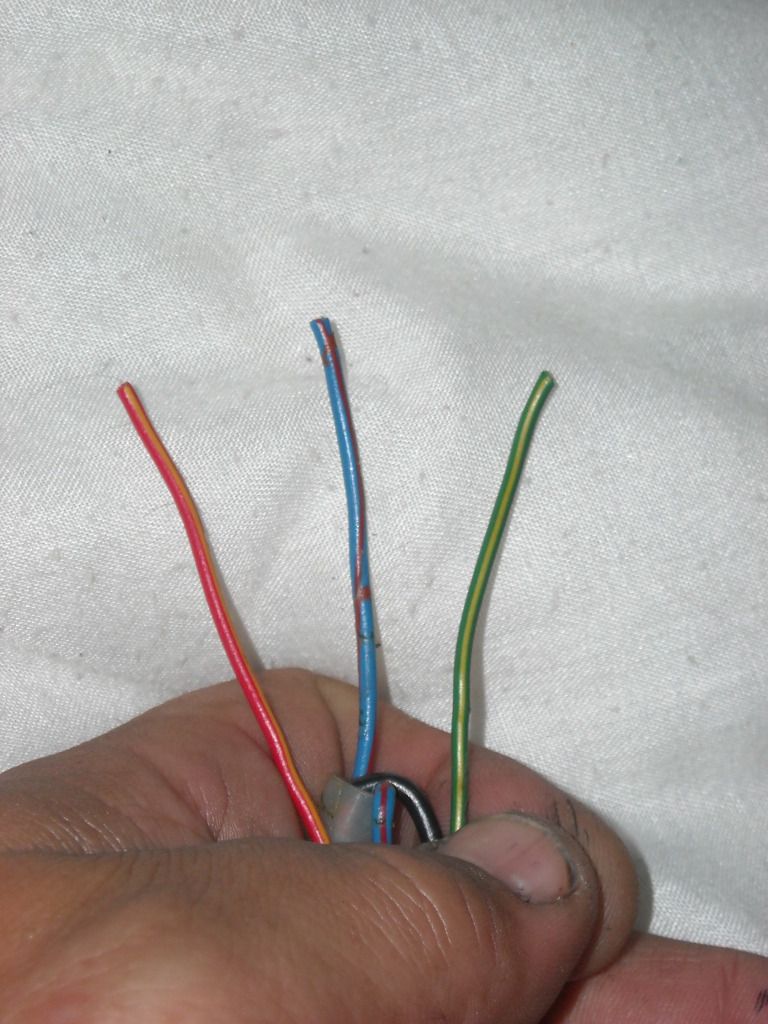
ON the BACK SIDE of the Rear Window Switch, WITHHHHHH the connector to the other side connected.... :
RED WITH YELLOW WIRE, as in the diagram, is "UP"
GREEN WITH YELLOW WIRE, as in the diagram, is "DOWN"
BLUE WITH RED STRIPE(and some red dots every inch), as in diagram, is "Switched Ground"
(PS> IF you don't have the other side of the connector... Only have the Male Pin side... Just know that the Blue with Red Stripe, in my case, would be just solid blue.
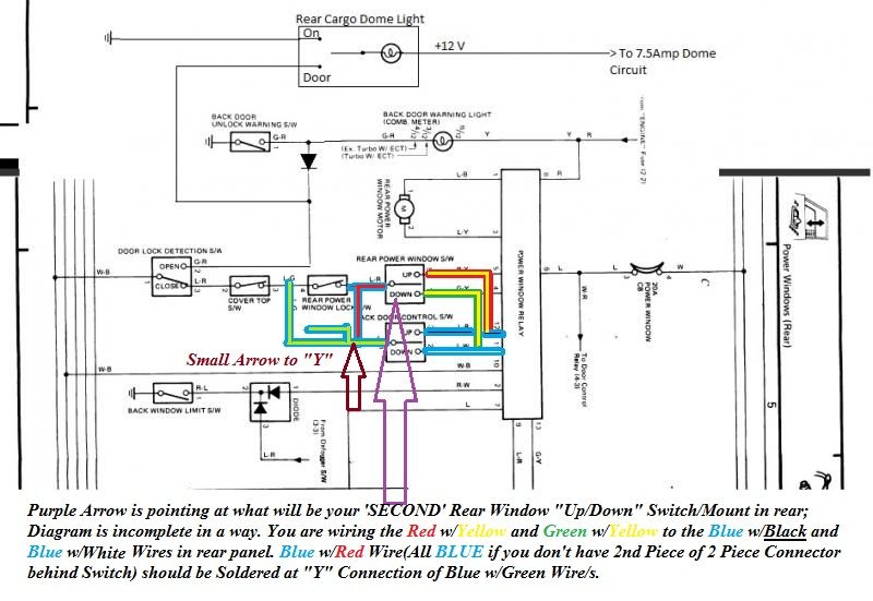
1. The Red wire with Yellow stripe jacks into the Blue with Black Stripe in the loom in the back panel, after the Window Relay Module. Green with Yellow Stripe into the Blue wire with White Stripe.
2. Blue with Red Stripe and Dot's every inch goes to the Blue wire with Green Stripe, right at the "Y" Connector would be fine. Good place to wrap it around and solder it to it.
3. Then, after speaking with RAD4Runner.... I think it would be good to have a SPST "ON/OFF" switch to simulate the "Window Lock Switch" up on the console, between the UP/DOWN and Rear Wiper Switches... This way, if I have the window in back open enough to REACH in, but not GET IN... no one can trip that switch and roll down the rear window... It will be SHUT OFF by the hidden added switch. I THINK RAD agreed with me on that, IIRC... I'll let him speak for himself, haha.
4. The dome circuit for the door, I'm going to go to the fuse block for 12V, Wiper motor for Ground and then wire in the "DOOR" portion will jack into the Green Wire with Red Stripe, between the "Back Door Unlock Warning Switch" and "Door Lock Detection Switch, with Diode in between, Negative side of Diode facing the Door Lock Detection Switch, positive facing the Back Door Unlock Warning Switch(As Dragon said, this will all become visible when pulling the cover off the tailgate, etc.... I'll get pics, tomorrow, if possible, Dragon.. THANKS MAN! )..... And I then should have the SAME effect as Bryan89(GRATEFUL, BRYAN! Your GREAT work is appreciated, much!)
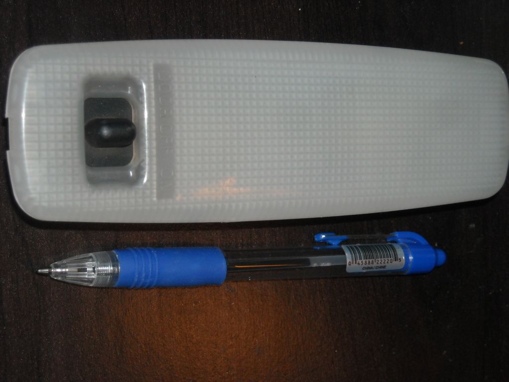
5. What I WILL likely be doing differently is this. I plan to add these into the panels in place of my old Deck Lamps.... I'm NOT keeping these Panels, most likely(they've been cut, etc.).. And because I have 3 of these(will use the best 2)...>>>
These mount without screws... So they are '3 WIRE'... which means I would just have to figure out Ground, and ground them right to something worthy.... Then wire them Using the Deck Lamps wiring(with Deck Lamp Mod) and then wire the door section to the same thing that the 2nd Gen Dome Light in the Wiper Cover will be wired for "DOOR".... They would still have "ON/OFF", so I wouldn't have to have all 3.. But it would SURELY be an improvement over the lil Deck Lamps, considering this type above uses a 36MM festoon... Which would allow a 12LED(6 on each side) 360* beam angle bulb(Just line the reflector well with foil).. and they'll be BRIGHTER than the 2nd Gen Dome(IF I NEEDED THEM, ya know?
Again, VERY MUCH enjoyed chatting with you, RAD4Runner.... and that you took all that time to help me out as well
Talk atcha all tomorrow.... Have a good one!
WOOT! I got it.... THANKS TO RAD4Runner and all of you.. But especially just now to RAD on the phone for a good AMOUNT OF time. Hopefully I was of some help with ideas, maybe 'thinking things out' when he does it.. But yeah,... it was MOSTLY him! hahaha.
Something about audibly talking it out it began to really sink in. I get what you just said about 'adding a keyed circuit' in a sense... and I've identified all the wires, etc.
THANK YOU, RAD4Runner, ... Dragon, Terry, Jason, Bryan89, EVERYONE who's hung in there with my schematically inept noggin! hahaha.
************************************************** **
ON the BACK SIDE of the Rear Window Switch, WITHHHHHH the connector to the other side connected.... :
RED WITH YELLOW WIRE, as in the diagram, is "UP"
GREEN WITH YELLOW WIRE, as in the diagram, is "DOWN"
BLUE WITH RED STRIPE(and some red dots every inch), as in diagram, is "Switched Ground"
(PS> IF you don't have the other side of the connector... Only have the Male Pin side... Just know that the Blue with Red Stripe, in my case, would be just solid blue.
1. The Red wire with Yellow stripe jacks into the Blue with Black Stripe in the loom in the back panel, after the Window Relay Module. Green with Yellow Stripe into the Blue wire with White Stripe.
2. Blue with Red Stripe and Dot's every inch goes to the Blue wire with Green Stripe, right at the "Y" Connector would be fine. Good place to wrap it around and solder it to it.
3. Then, after speaking with RAD4Runner.... I think it would be good to have a SPST "ON/OFF" switch to simulate the "Window Lock Switch" up on the console, between the UP/DOWN and Rear Wiper Switches... This way, if I have the window in back open enough to REACH in, but not GET IN... no one can trip that switch and roll down the rear window... It will be SHUT OFF by the hidden added switch. I THINK RAD agreed with me on that, IIRC... I'll let him speak for himself, haha.
4. The dome circuit for the door, I'm going to go to the fuse block for 12V, Wiper motor for Ground and then wire in the "DOOR" portion will jack into the Green Wire with Red Stripe, between the "Back Door Unlock Warning Switch" and "Door Lock Detection Switch, with Diode in between, Negative side of Diode facing the Door Lock Detection Switch, positive facing the Back Door Unlock Warning Switch(As Dragon said, this will all become visible when pulling the cover off the tailgate, etc.... I'll get pics, tomorrow, if possible, Dragon.. THANKS MAN! )..... And I then should have the SAME effect as Bryan89(GRATEFUL, BRYAN! Your GREAT work is appreciated, much!)
5. What I WILL likely be doing differently is this. I plan to add these into the panels in place of my old Deck Lamps.... I'm NOT keeping these Panels, most likely(they've been cut, etc.).. And because I have 3 of these(will use the best 2)...>>>
These mount without screws... So they are '3 WIRE'... which means I would just have to figure out Ground, and ground them right to something worthy.... Then wire them Using the Deck Lamps wiring(with Deck Lamp Mod) and then wire the door section to the same thing that the 2nd Gen Dome Light in the Wiper Cover will be wired for "DOOR".... They would still have "ON/OFF", so I wouldn't have to have all 3.. But it would SURELY be an improvement over the lil Deck Lamps, considering this type above uses a 36MM festoon... Which would allow a 12LED(6 on each side) 360* beam angle bulb(Just line the reflector well with foil).. and they'll be BRIGHTER than the 2nd Gen Dome(IF I NEEDED THEM, ya know?
Again, VERY MUCH enjoyed chatting with you, RAD4Runner.... and that you took all that time to help me out as well
Talk atcha all tomorrow.... Have a good one!
Last edited by ChefYota4x4; 10-11-2012 at 10:13 AM.
 10-11-2012, 09:59 AM
#4965
YOUR head hurts? hahaha.. JK... "MINE TOO" will do!  ........ Actually, the pain is receding every minute more that I absorb this! AND, ...the cool thing, Flea, is this gives me LOTS of options on the amount of 'DOO-DATS' I can do... And Doodats, as everyone knows... Well, THEY ROCK! hahaha.
Flea had me giggling a lil bit there.... Then I read this, and as simple and clean humor as it was, ....for some reason, I nearly spat my coffee on the screen, no kidding! hahaha.
Thanks, Grego, I needed that. Hope you're doing well, sir!
........ Actually, the pain is receding every minute more that I absorb this! AND, ...the cool thing, Flea, is this gives me LOTS of options on the amount of 'DOO-DATS' I can do... And Doodats, as everyone knows... Well, THEY ROCK! hahaha. Flea had me giggling a lil bit there.... Then I read this, and as simple and clean humor as it was, ....for some reason, I nearly spat my coffee on the screen, no kidding! hahaha.
Thanks, Grego, I needed that.
Hope you're doing well, sir!
10-11-2012, 12:10 PM
#4967
10-11-2012, 12:45 PM
#4968
Hello everyone,
Wanted to share something on here that I was working on....
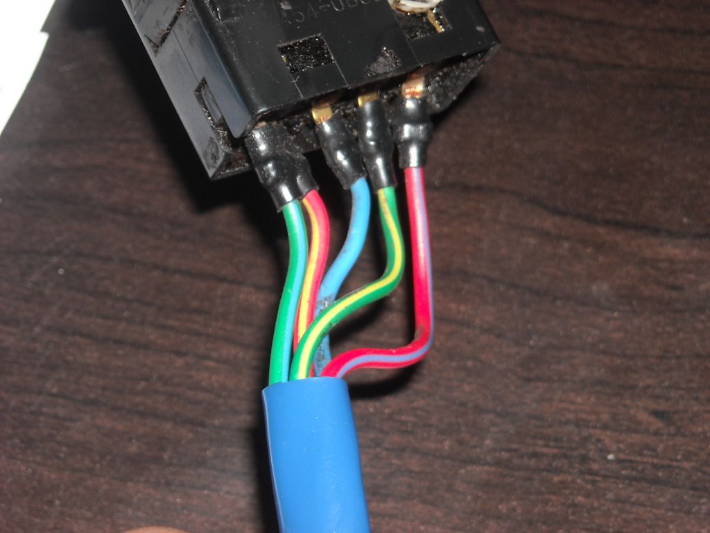
1. THESE ARE the only wires you'll need of the 5 available on the "Rear Window Switch" you may be adding in........
If you are tapping right onto the Male pins or removing the main switch connector all together(Going to Free Standing Wires from the back of the Switch)... You will use the ALL BLUE wire instead of the Blue and Red(It's the same PIN.... just changes colors on the 'OUTSIDE' of the second portion of the 2 connector pieces. HOWEVER, the Red/Yellow= UP and Green/Yellow=DOWN wires are the same color coding on both sides of connectors)....
Here is a "PAINT" version of the Diagram that we've copied from Byran89... (His diagram pic is 'cropped' and doesn't include the 13 Pin "Window Control Module" that's behind the driver seat in the forward most rear panel... BUT, it also shows the "DOME ADD IN" method... I'll do a "PAINT" shop pic of the Dome Add in, all colored, etc., as well ).... So I couldn't point the wires there, .... but that's ok, you have the picture that RAD4Runner posted(GREAT! ) to explain the where you tap in the 2, "UP/DOWN" wires... and also a picture of the "Y" Connector, which is where I'll 'wrap and solder' and electrical tape and before rewrapping the loom. I'll post all 3 pics......
*********
BELOW, in his original quotes, ARE THE PICS AND FULL INFO FROM RAD4Runner, explaining where to tap in. BUT, also PIGGYBACK onto the "Y"Connector with the Blue/Green Wire/s, using your "BLUE/RED" wire (ALL BLUE if you're just cutting away all connectors). Use my pictures of the Wiring Colors
*********
Wanted to share something on here that I was working on....
1. THESE ARE the only wires you'll need of the 5 available on the "Rear Window Switch" you may be adding in........
If you are tapping right onto the Male pins or removing the main switch connector all together(Going to Free Standing Wires from the back of the Switch)... You will use the ALL BLUE wire instead of the Blue and Red(It's the same PIN.... just changes colors on the 'OUTSIDE' of the second portion of the 2 connector pieces. HOWEVER, the Red/Yellow= UP and Green/Yellow=DOWN wires are the same color coding on both sides of connectors)....
Here is a "PAINT" version of the Diagram that we've copied from Byran89... (His diagram pic is 'cropped' and doesn't include the 13 Pin "Window Control Module" that's behind the driver seat in the forward most rear panel... BUT, it also shows the "DOME ADD IN" method... I'll do a "PAINT" shop pic of the Dome Add in, all colored, etc., as well
).... So I couldn't point the wires there, .... but that's ok, you have the picture that RAD4Runner posted(GREAT! ) to explain the where you tap in the 2, "UP/DOWN" wires... and also a picture of the "Y" Connector, which is where I'll 'wrap and solder' and electrical tape and before rewrapping the loom. I'll post all 3 pics...... *********
BELOW, in his original quotes, ARE THE PICS AND FULL INFO FROM RAD4Runner, explaining where to tap in. BUT, also PIGGYBACK onto the "Y"Connector with the Blue/Green Wire/s, using your "BLUE/RED" wire (ALL BLUE if you're just cutting away all connectors). Use my pictures of the Wiring Colors
*********
Correct. Look at this part of harness (between 2 rollbar up tubes), or farther aft depending on where you want your new switch to be.

Look for light blue wire with white stripe and light blue wire with black stripe. Verify they go to Pins 11 & 12 of Rear Window Relay.


"Y" splice just forward of Top Off switch and connected to switch.
This splice is "ground" for Up/Down switch, but put lock switch between this and Up/Dn switch.

Piece of cake, or whatever Chef's fave pastry is
BTW, while you're working on that side, try if you could move harness completely behind pillars, instead of snaking to front and behind them. Would make further mods easier (i.e., new panels, mounting speakers, etc.) I already did it on the right side. Yeah, even sound proofing. With harness behind pillars, you can easily hang sound damping foam curtain behind pillars and panel and make it easy to move aside to work around.
Look for light blue wire with white stripe and light blue wire with black stripe. Verify they go to Pins 11 & 12 of Rear Window Relay.
"Y" splice just forward of Top Off switch and connected to switch.
This splice is "ground" for Up/Down switch, but put lock switch between this and Up/Dn switch.
Piece of cake, or whatever Chef's fave pastry is
BTW, while you're working on that side, try if you could move harness completely behind pillars, instead of snaking to front and behind them. Would make further mods easier (i.e., new panels, mounting speakers, etc.) I already did it on the right side. Yeah, even sound proofing. With harness behind pillars, you can easily hang sound damping foam curtain behind pillars and panel and make it easy to move aside to work around.
10-11-2012, 02:20 PM
#4969
[QUOTE=ChefYota4x4;51984378]
Yeah, schematic shows nothing connected to those two "unneeded" wires. However, I measured tens of ohms resistance between them. Therefore, so now I suspect they are for illuminated switches. Could anyone whose 4Runners' console switches are illuminated verify?
Yeah, schematic shows nothing connected to those two "unneeded" wires. However, I measured tens of ohms resistance between them. Therefore, so now I suspect they are for illuminated switches. Could anyone whose 4Runners' console switches are illuminated verify?
10-11-2012, 02:44 PM
#4970
Hey RAD!  ...
...
You know, When looking at the window control..... even the schematic... I think I see them in the loom(even VISIBLY in your pics of the Window Controller wires>>>???)
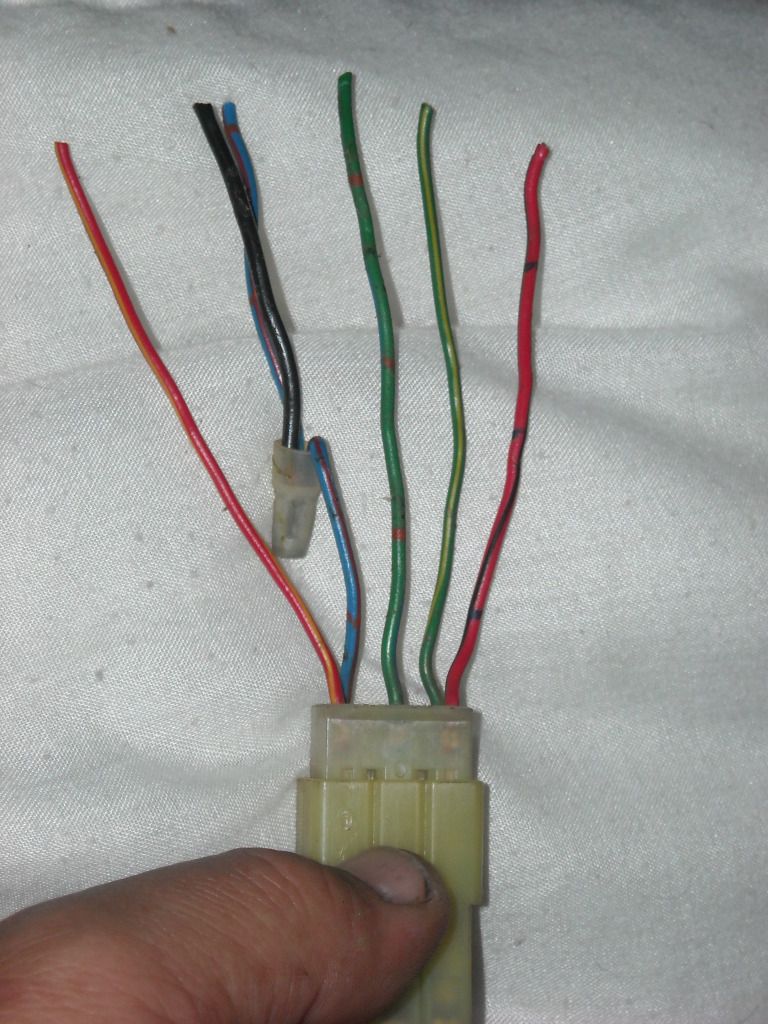
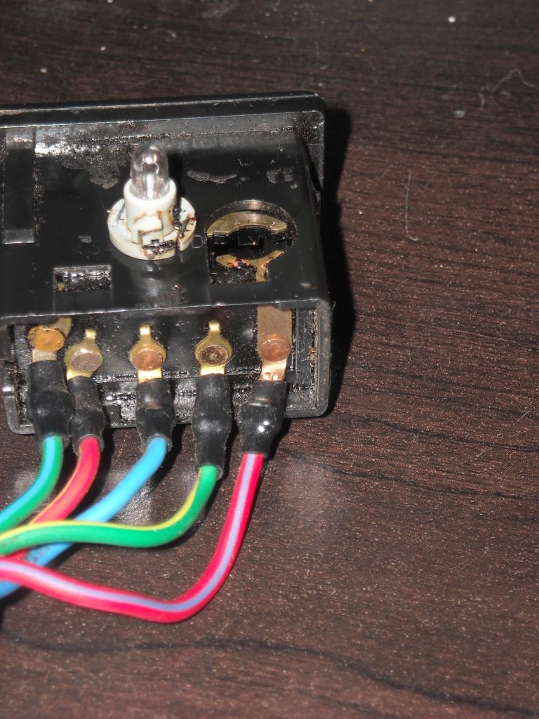
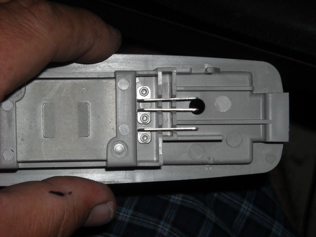
In the schematic.... The RED w/BLUE Stripe(one of the unused ones on the Switch) goes to the "Back Window Limit Switch".... SO, My guess would be, "it's wired back through the switch to prevent it from working when the Wiper Blade Contacts on the Roof and Wiper itself are not making contact(remember I was telling you, when the wiper isn't touching, even when not on, it stops the window from opening/switch from working"..) ... ???
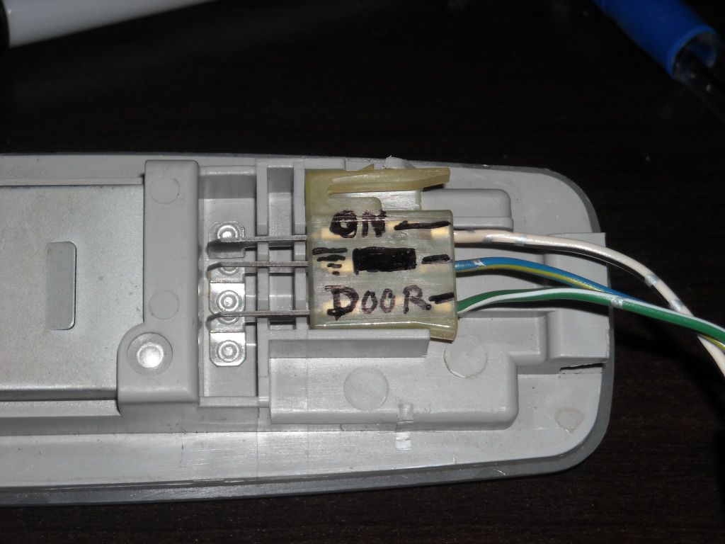
The GREEN w/BLUE stripe at the Connector (G-L in Schematic) doesn't appear to be.... there! lol. ....NOT sure... as, even after the connector, it's RED w/Black Stripe... Which I neither see represented. BUT, in your pic of the window controller box... I think I see the RED w/BLACK striped wire??? .......... Here's a pic of the wires AT THE Switch, rather than with the wires how they're represented on the OTHER side of the connector, which I have in those pics....
... You know, When looking at the window control..... even the schematic... I think I see them in the loom(even VISIBLY in your pics of the Window Controller wires>>>???)
In the schematic.... The RED w/BLUE Stripe(one of the unused ones on the Switch) goes to the "Back Window Limit Switch".... SO, My guess would be, "it's wired back through the switch to prevent it from working when the Wiper Blade Contacts on the Roof and Wiper itself are not making contact(remember I was telling you, when the wiper isn't touching, even when not on, it stops the window from opening/switch from working"..) ... ???
The GREEN w/BLUE stripe at the Connector (G-L in Schematic) doesn't appear to be.... there! lol. ....NOT sure... as, even after the connector, it's RED w/Black Stripe... Which I neither see represented. BUT, in your pic of the window controller box... I think I see the RED w/BLACK striped wire??? .......... Here's a pic of the wires AT THE Switch, rather than with the wires how they're represented on the OTHER side of the connector, which I have in those pics....
Last edited by ChefYota4x4; 10-11-2012 at 03:05 PM.
10-11-2012, 03:06 PM
#4971
PS> ...... I'm not sure, unless it's wired through the Switch I'll be adding, that it would be wise to include the "LIGHT" portion.... And heck, it might be lighted anyhow, just by wiring up the 3, ya know? Not that it's a HUGE power drainer, lol... BUT, after a few weeks or more of being 'CONSTANTLY ON'??? Not sure.
Although, it would be VERY cool to have it lit while you're sleeping back there. I guess no one mentions, when they've added it, that 'IT'S LIT, TOO ' HAHAHA...
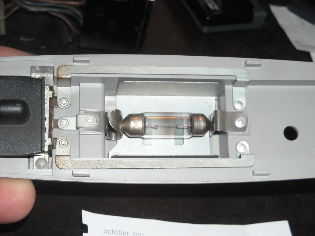
PSS> My GUESS, RAD, ... is that the RED w/Blue Stripe wire in the pic above? It controls the light. Look above that terminal... Isn't that the 'LIGHT APPARATUS' plug that's just above it?
AH HAHHHHHHHHHHHHHHHH! ... I think I'm right, RAD...........>>>>>>>>>>
Although, it would be VERY cool to have it lit while you're sleeping back there. I guess no one mentions, when they've added it, that 'IT'S LIT, TOO
' HAHAHA...PSS> My GUESS, RAD, ... is that the RED w/Blue Stripe wire in the pic above? It controls the light. Look above that terminal... Isn't that the 'LIGHT APPARATUS' plug that's just above it?
AH HAHHHHHHHHHHHHHHHH!
... I think I'm right, RAD...........>>>>>>>>>>
Last edited by ChefYota4x4; 10-11-2012 at 03:14 PM.
10-11-2012, 03:20 PM
#4972
So, maybe if I just wire the RED w/BLUE striped wire in with the BLUE....It'll wind up powered(the LIGHT)... THEN, having the second SPST Switch wired in as a "MOCK UP- REAR POWER WINDOW LOCK S/W", whenever I have it 'OFF', ...NO LIGHT >>>>>????
10-11-2012, 04:29 PM
#4973
Yep, it's a tiny bulb (I thought that grey circular thing was some manufacturing batch marker - LOL!). I would not use it there in the back, though, 'cause the way you intend it for means it would have to be always on, even when ignition is off meaning it wold drain battery. Unless you add another switch to illuminate the switch only when camping in deck. I think that would be too much hardware, work and trouble for a minor benefit. Now wiring the light for the console switch would make better sense. Wire it to same circuit that illuminates dash.
10-11-2012, 05:43 PM
#4974
Contributing Member
Hey and good night Chef! All this wiring talk is turning my brain into spaghetti. Awesome help you've got.
10-11-2012, 06:02 PM
#4975
HEY, that's right.... the Switch lights all dim with the dimmer switch... Thanks
So, that sounds like a good idea... Thanks for the funny, educating lashing hahaha.
**************
Hey Hab! Sup Sassypants? .... How have you been? Sorry bout the Spaghetti Soup in the Brain I've caused...  ..... I'm just now untangling the proverbial "Christmas Tree Lights" myself!
So, that sounds like a good idea... Thanks for the funny, educating lashing
hahaha.**************
Hey Hab! Sup Sassypants?
.... How have you been? Sorry bout the Spaghetti Soup in the Brain I've caused... ..... I'm just now untangling the proverbial "Christmas Tree Lights" myself!
Last edited by ChefYota4x4; 10-11-2012 at 06:06 PM.
10-11-2012, 09:09 PM
#4976
NOW, ..... since I have no Lexan, like someoneeeee I know,  hahahaha....... help me finalize a nice set of panels(from the that will support a 10" Sub and maybe inverter?)
I REALLY like some of the panels I've seen... Even Bryan89... But I'm not sure I want any form of Metal, like Bryan, so even Aluminum is out(pricey too).... So I think my plan, so far, as we spoke on, RAD? >>>
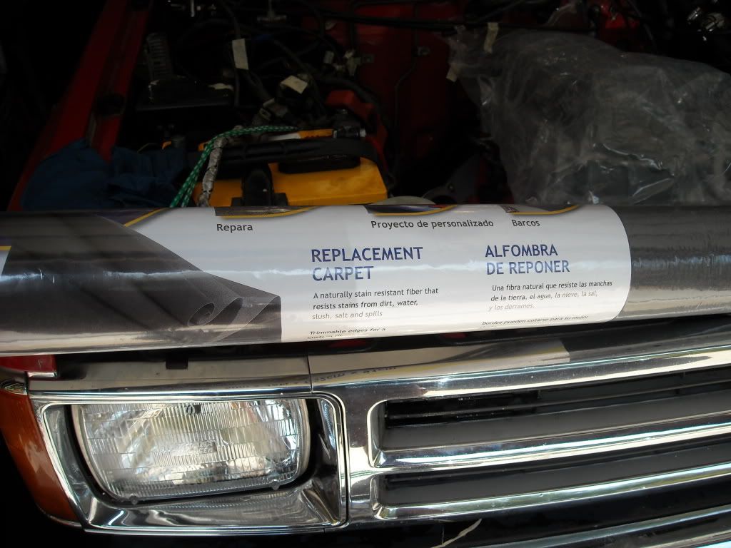
1. Get 1/4" Plywood covered with a good sealer and then covered with a good charcoal colored, THINLY padded carpet.(I have quite bit of Charcoal Gray Auto Carpet)>>>
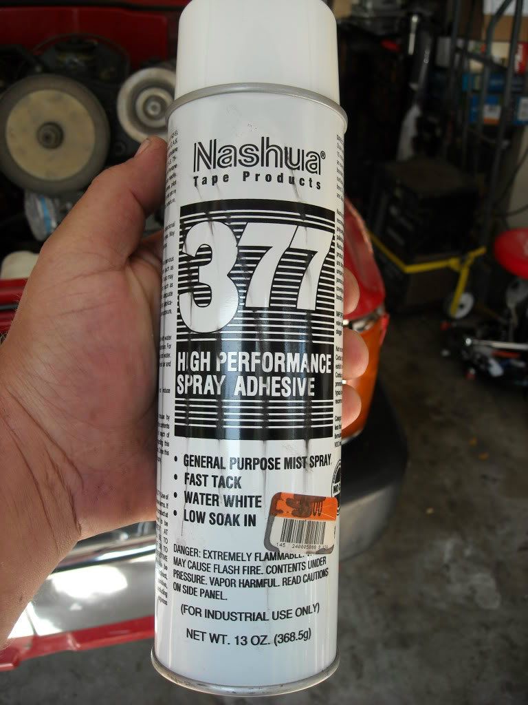
I also have this stuff, which is INTENSE adhesive... But I wouldn't use to adhere CARPET to WHATEVER is right beneath it... as it COULD soak through and leave stains/imperfections, ya know?... BUT, I could use it to adhere the padding or idea I'm going to STEAL from RAD and Nervo.... (Zero Absorbancy Foam.....Sorry, I know I'm wording that wrong, haha) to the wood.) Then I'd likely use P&S or something else behind that on the actual 'body'. behind the panels.
2. This could all(Wood/Carpet/Heat Sheilded Padding on both sides on inside) act as a Sub Enclosure... And, after speaking with RAD on that... I think that's what I'd do, rather than building an enclosure.
3. Also; With the Wood sides, I should be able to mount not only the 10" Sub, .... but also one of the Power Inverters I've wanted to mount permanently, like RBX did (RBX has stock panels, IIRC... but he still mounted the Inverter IN the panel and some "PLUG INS" on the panel itself? (RBX will have a visit from me today, just to see for myself.... hahaha.. Then I'll come back and edit.)
A large point in all this for me? I'm REALLY enjoying myself! (no, not every second of the journey, hehe.. BUT, the learning new things portion? ROCKS! lol.)THANKS, very much, once again, to all the people who've given me a hand/props/advice... and ESPECIALLY helped me personally to figure something out in a way that 'SINKS IN FOR ME!'
hahahaha....... help me finalize a nice set of panels(from the that will support a 10" Sub and maybe inverter?)I REALLY like some of the panels I've seen... Even Bryan89... But I'm not sure I want any form of Metal, like Bryan, so even Aluminum is out(pricey too).... So I think my plan, so far, as we spoke on, RAD? >>>
1. Get 1/4" Plywood covered with a good sealer and then covered with a good charcoal colored, THINLY padded carpet.(I have quite bit of Charcoal Gray Auto Carpet)>>>
I also have this stuff, which is INTENSE adhesive... But I wouldn't use to adhere CARPET to WHATEVER is right beneath it... as it COULD soak through and leave stains/imperfections, ya know?... BUT, I could use it to adhere the padding or idea I'm going to STEAL from RAD and Nervo.... (Zero Absorbancy Foam.....Sorry, I know I'm wording that wrong, haha) to the wood.) Then I'd likely use P&S or something else behind that on the actual 'body'. behind the panels.
2. This could all(Wood/Carpet/Heat Sheilded Padding on both sides on inside) act as a Sub Enclosure... And, after speaking with RAD on that... I think that's what I'd do, rather than building an enclosure.
3. Also; With the Wood sides, I should be able to mount not only the 10" Sub, .... but also one of the Power Inverters I've wanted to mount permanently, like RBX did
(RBX has stock panels, IIRC... but he still mounted the Inverter IN the panel and some "PLUG INS" on the panel itself? (RBX will have a visit from me today, just to see for myself.... hahaha.. Then I'll come back and edit.) A large point in all this for me? I'm REALLY enjoying myself! (no, not every second of the journey, hehe.. BUT, the learning new things portion? ROCKS! lol.)THANKS, very much, once again, to all the people who've given me a hand/props/advice... and ESPECIALLY helped me personally to figure something out in a way that 'SINKS IN FOR ME!'
Last edited by ChefYota4x4; 10-11-2012 at 09:11 PM.
10-11-2012, 09:31 PM
#4977
Console Switch All Set up for illumination :)
Also just found out that Window Lock switch has green LED inside. Rear wiper/washer switch probably has one, too. Just a matter of wiring them up. I wonder if anyone owns a 4Runner, or other Yotas that use same switches, with those switches lit.
10-11-2012, 09:39 PM
#4978
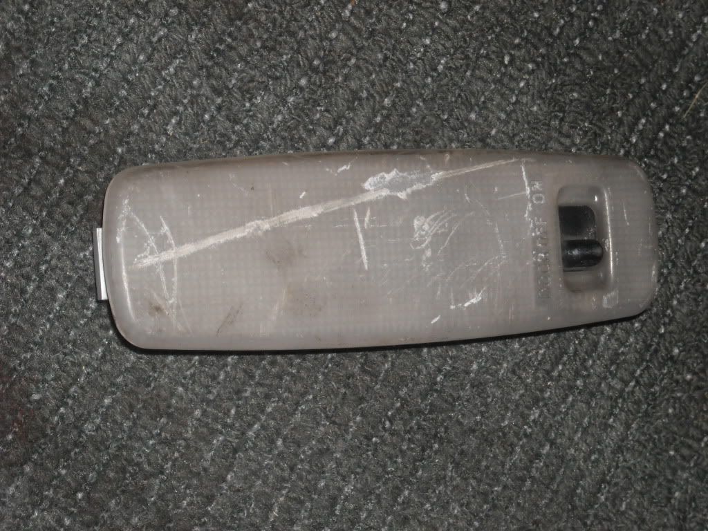
OK, .... so I took the 2nd Gen 4Runner Rear Wiper Motor and Speaker Cover Dome Light and applied some of the tests with the Multi-Meter that RAD was showing me... I also took pics of the process/how the connector looks, etc. >>>>
Green Clip I use is to Positive and Yellow to Ground on the Meter probes....
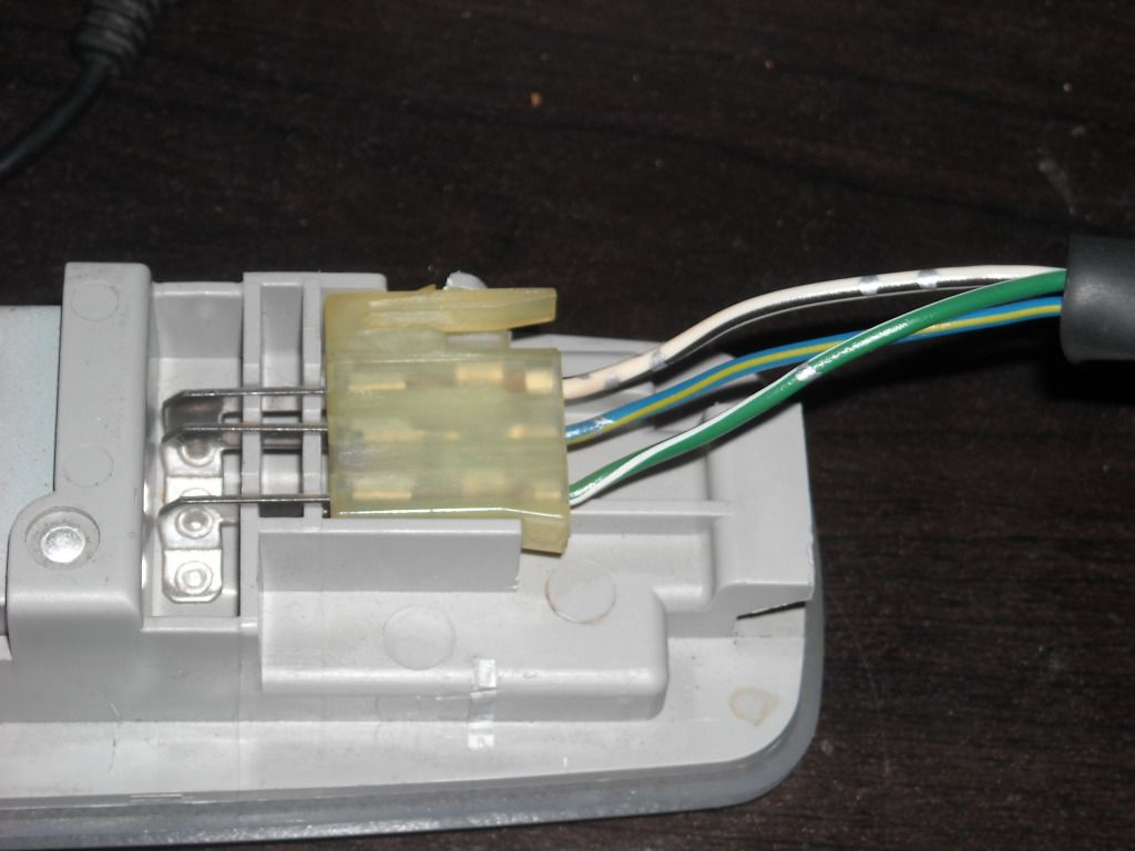
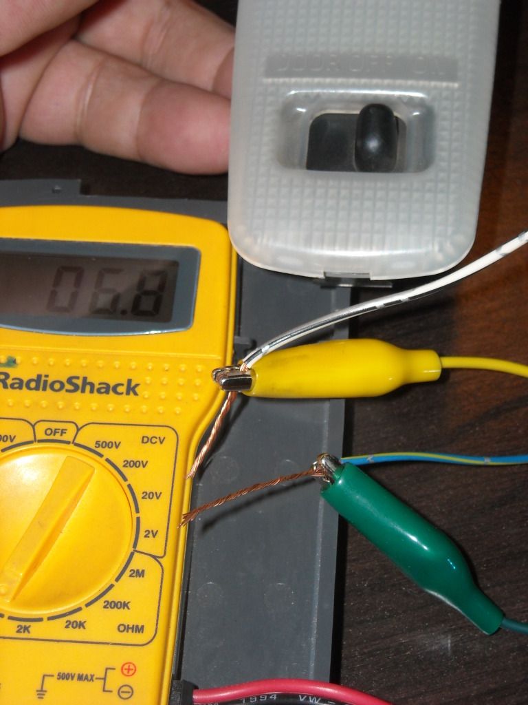
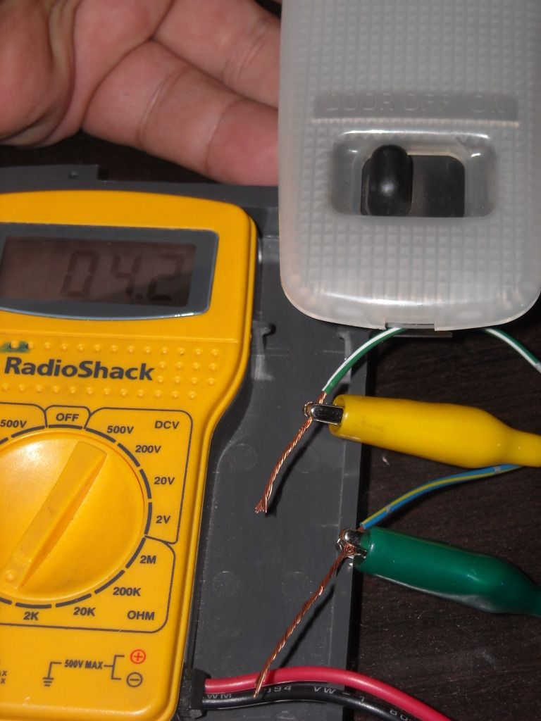
This is checking both sides with the Lever set to OFF......
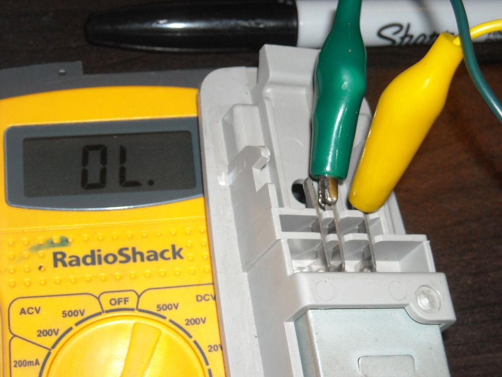
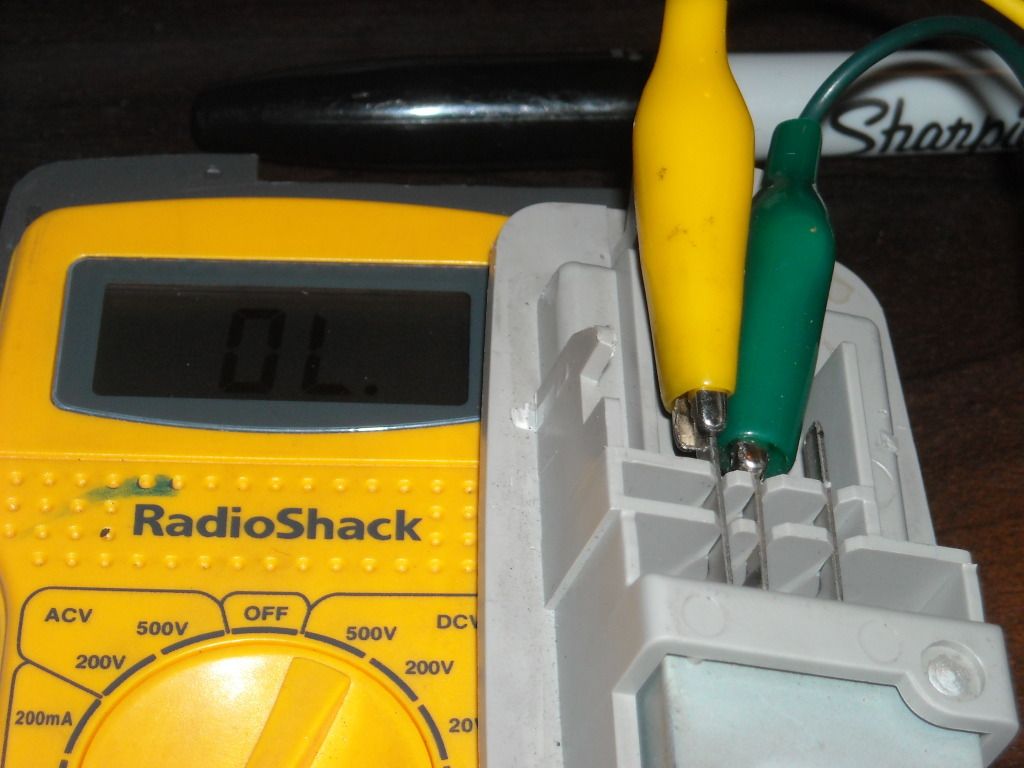
Soooooooo, ..... do I have this right???? >>>>>>>
*************************************
Far as the Lights in the Switches, RAD...>>>>>>>>>
Yeah, that's what I was saying about the switches all lighting up brighter with my new to me Dimmer. Anyway, are you saying your switches weren't lighting up before?
PSS> Gonna getcha that switch in the mail tomorrow, man!
RAD, ...would it work using a SPARE rear window lock switch in the rear? I think a safety style like I have in my dash for the off road lights is better.... it can't be accidentally switched off. But hypothetically, wouldn't it have the same effect as any flip switch?
Green Clip I use is to Positive and Yellow to Ground on the Meter probes....
This is checking both sides with the Lever set to OFF......
Soooooooo, ..... do I have this right???? >>>>>>>
*************************************
Far as the Lights in the Switches, RAD...>>>>>>>>>
Yeah, that's what I was saying about the switches all lighting up brighter with my new to me Dimmer. Anyway, are you saying your switches weren't lighting up before?
PSS> Gonna getcha that switch in the mail tomorrow, man!
RAD, ...would it work using a SPARE rear window lock switch in the rear? I think a safety style like I have in my dash for the off road lights is better.... it can't be accidentally switched off. But hypothetically, wouldn't it have the same effect as any flip switch?
Last edited by ChefYota4x4; 10-11-2012 at 10:00 PM.
10-11-2012, 09:41 PM
#4979
Registered User
mark!!! just checkin on ya buddy, been in hibernation since the sell of my 82, so i decided to check in! when the SAS and 5.71s and 44s man?!!?! still looking good evemn though its still IFS!
10-11-2012, 09:50 PM
#4980
Not that I'd never have something bigger/taller/hugerer, haha... But it would be a weekend rig. Ya know?
Hope you're doing well, Josh... Take care, man. Check in more often and lemme know how school and such are, ya know?


