BlazeN8's 1986 4Runner Build-Up Thread
 01-03-2014, 03:49 PM
#341
Registered User
Thread Starter
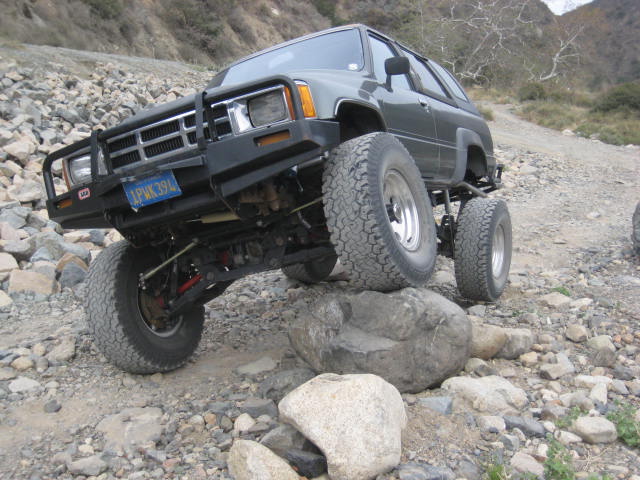
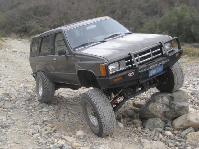
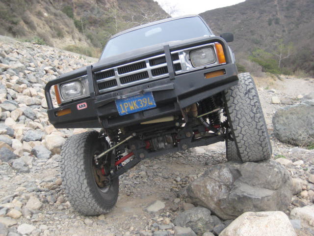
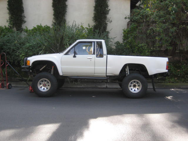
I jacked up the front 3" This is how it would sit with the Mega Travel. I would also be stepping up the tire from a 33 to a 35. It will definitely clear 35s with the Mega, a 2" body lift, and fiberglass fenders. When I have Deaver build the new rear leaf pack (off the Chevy main leaf) I'd have them bump up the lift 1"
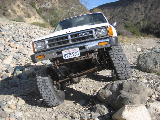
and a before reference photo
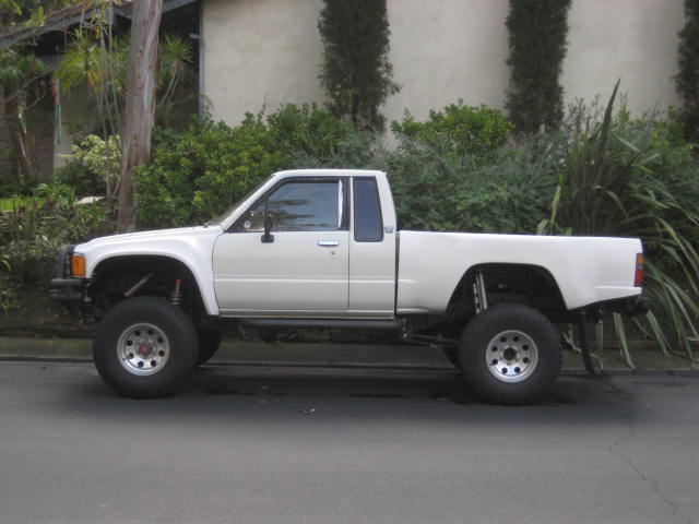
and a before reference photo
Last edited by BlazeN8; 01-03-2014 at 04:10 PM.
 01-03-2014, 04:05 PM
#343
Registered User
Thread Starter
I think its worth trying out!
In the before photo the front is cranked in a little more than I liked to sit level with the rear. I estimate 4" of down travel and 7" of up travel in this photo. I had installed thicker droop stops to save my CVs as I'd been running in 4wd. With the Mega it would be set at balance of 8" up travel and 7" down travel with no CV issues.
In the before photo the front is cranked in a little more than I liked to sit level with the rear. I estimate 4" of down travel and 7" of up travel in this photo. I had installed thicker droop stops to save my CVs as I'd been running in 4wd. With the Mega it would be set at balance of 8" up travel and 7" down travel with no CV issues.
Last edited by BlazeN8; 01-03-2014 at 04:08 PM.
01-05-2014, 02:48 PM
#344
Registered User
Like the mega travel setup. I'm wondering if I would have room for the uca pivots moved in the 2.5" on my second gen pu.
I have a 3.4 swap and headers that will make it tight.
Have to fab a brace across the shock hoops too.
The track width is the same as the standard LT kit?
The R and D of this kit makes interesting reading.
I have a 3.4 swap and headers that will make it tight.
Have to fab a brace across the shock hoops too.
The track width is the same as the standard LT kit?
The R and D of this kit makes interesting reading.
01-05-2014, 04:01 PM
#346
Registered User
Thread Starter
Like the mega travel setup. I'm wondering if I would have room for the uca pivots moved in the 2.5" on my second gen pu.
I have a 3.4 swap and headers that will make it tight.
Have to fab a brace across the shock hoops too.
The track width is the same as the standard LT kit?
The R and D of this kit makes interesting reading.
I have a 3.4 swap and headers that will make it tight.
Have to fab a brace across the shock hoops too.
The track width is the same as the standard LT kit?
The R and D of this kit makes interesting reading.
01-05-2014, 04:15 PM
#347
Registered User
Thread Starter
I attempted what your proposing in my design process and the complication is with the steering geometry. If you did move forward you would need to either relocate the Idler and Pitman or you could shorten the relay arms. Relocating of the steering box would be extremely difficult as the frame is....well just look at it for yourself. Shortening the relay arms would change the arc geometry in a way that may not work.
01-05-2014, 04:28 PM
#348
I attempted what your proposing in my design process and the complication is with the steering geometry. If you did move forward you would need to either relocate the Idler and Pitman or you could shorten the relay arms. Relocating of the steering box would be extremely difficult as the frame is....well just look at it for yourself. Shortening the relay arms would change the arc geometry in a way that may not work.
guess im gonna have to look at trimming the kick panels lol
01-05-2014, 04:37 PM
#349
Registered User
Thread Starter
Moving the idler unit forward isn't a big deal, but the pitman /steering box is up against the radiator support bulkhead and there are some issues with the frame brackets with body mounts and such.
Kick panel modification with a drop bracket kit and 35s is minimal. Just hammer the vertical body seam flat and trim and fold back the sheet metal on the fender.
Kick panel modification with a drop bracket kit and 35s is minimal. Just hammer the vertical body seam flat and trim and fold back the sheet metal on the fender.


 01-08-2014, 08:40 PM
#351
Registered User
Thread Starter
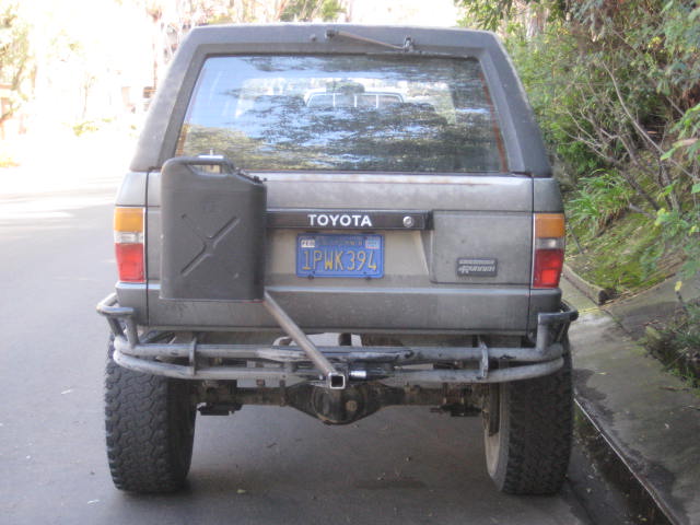
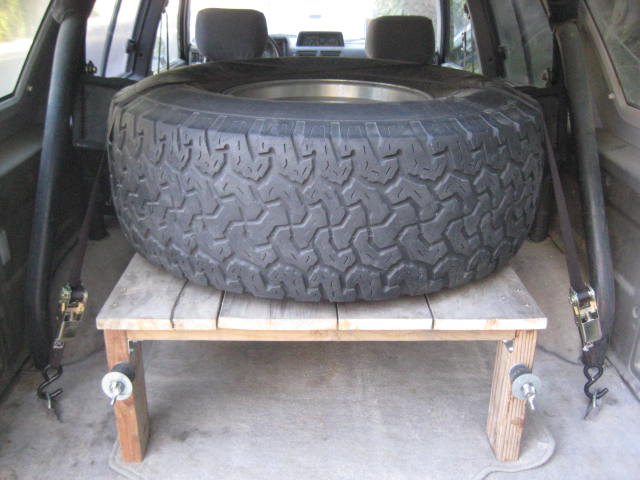
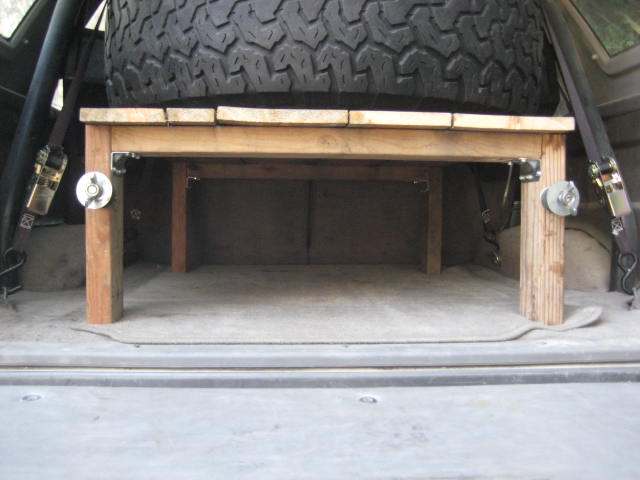
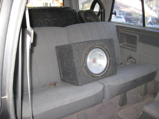
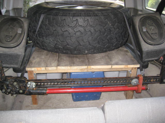
Here is how I stow my hi-hift Jack and spare tire.
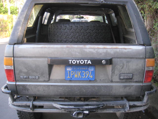
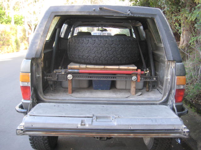
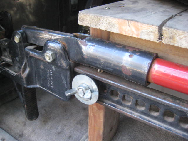
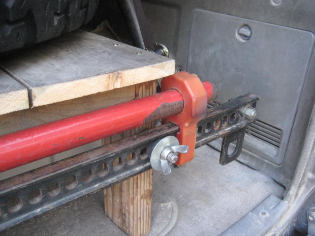
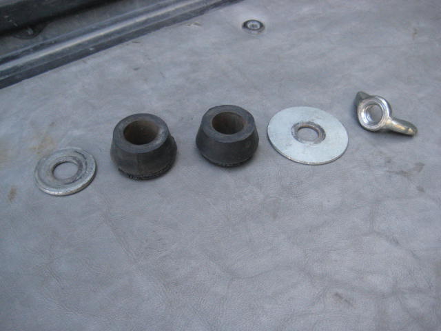
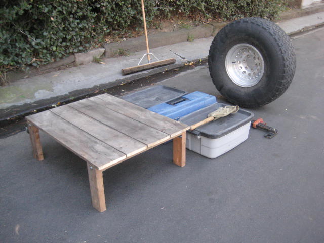
The tire shelf is an old pallet I attached legs to. The jack is secured with some 1/2" all-thread, fender washers, some old shock bushings, and a couple of wing nuts.

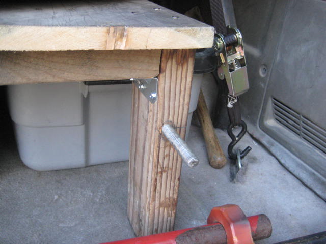
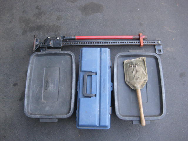
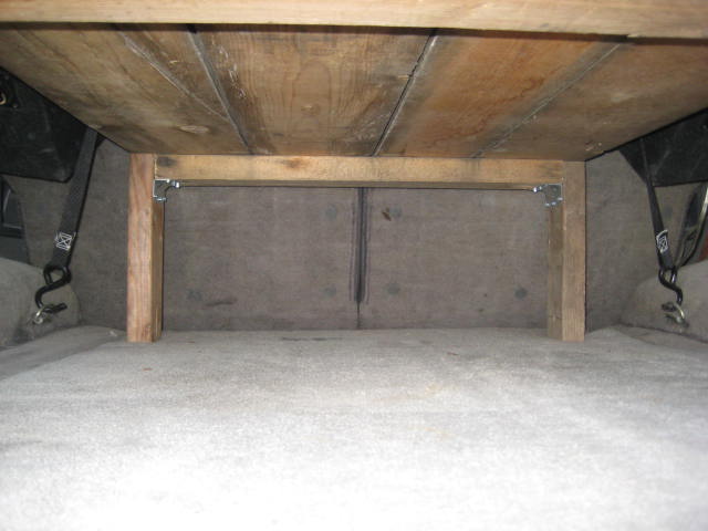
Under the shelf is a tool box, parts bin LH, parts bin RH and army shovel.
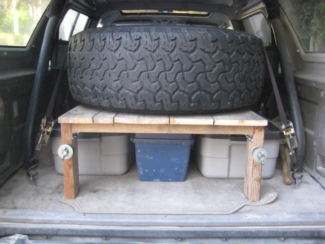
The spare tire sits on top of the shelf and the whole thing is held down with a couple of crossed ratchet straps. The straps are anchored to the (4) factory hooks at the corners.

Of course this isn't everything but its some of the bigger essential items. Off hand some other things I pack are a tent, sleeping bag, cooler, air compressor, tow strap, jumper cables, food, water, cloths, etc. The smaller gear items I like to stow in old duffle bags and back packs and infill through out the rear cargo area and back seat as needed.
As far a keeping everything on the interior, except fuel can, its not too bad. The table will be nice around the campsite.
One thing I did reconfigure is spinning the table around 180 degrees so the jack is directly behind the back seat. This is nice as I don't have to remove the jack to get to the bottom shelf. But the down side is crawling in the back and folding down the rear seat to get the jack out.
The tire shelf is an old pallet I attached legs to. The jack is secured with some 1/2" all-thread, fender washers, some old shock bushings, and a couple of wing nuts.
Under the shelf is a tool box, parts bin LH, parts bin RH and army shovel.
The spare tire sits on top of the shelf and the whole thing is held down with a couple of crossed ratchet straps. The straps are anchored to the (4) factory hooks at the corners.
Of course this isn't everything but its some of the bigger essential items. Off hand some other things I pack are a tent, sleeping bag, cooler, air compressor, tow strap, jumper cables, food, water, cloths, etc. The smaller gear items I like to stow in old duffle bags and back packs and infill through out the rear cargo area and back seat as needed.
As far a keeping everything on the interior, except fuel can, its not too bad. The table will be nice around the campsite.
One thing I did reconfigure is spinning the table around 180 degrees so the jack is directly behind the back seat. This is nice as I don't have to remove the jack to get to the bottom shelf. But the down side is crawling in the back and folding down the rear seat to get the jack out.
01-26-2014, 10:03 PM
#352
Registered User
Thread Starter
I've been keeping my eyes open for coil springs. Yesterday I ran across a pair on Craig’s List. Oh boy, a pair of King 18" 400lb for $50. I wasn't sure that going from 16" 500lb to 18" 400lb is going to work but the price was right. The 16" 500lb spring I had been using was a bit short so I was using a tender spring to add length. This set up had way too much pre-load (1.75") and was really unstable as the first few inches of spring movement were acting on the 6" spring.
Here is a photo of the C.L. springs next to the ones I had. I'm not sure why the new Kings were powder coated black? The silver 4" 500lb Eibach tender springs and black spring dividers are something I had from a previous set up on another ride.
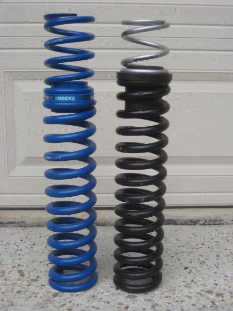
Today I swapped out the springs. The new set up used the 18" spring in single rate and the 4" spring for tender. I installed the main spring and hand tightened the secondary lock out nuts against the spring divider with no pre-load. I was surprised when I lowered the rig and applied weight on the spring that the ride height was actually 1" higher on the passenger side and 1-1/2" higher on the driver side than before. Great, now the front is level with the rear. I then added 1/4" pre-load to the passenger side to sit level from side to side. Next I added 1/2" pre-load to the spring collar to snug the tender spring.
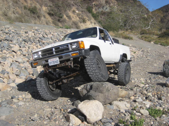
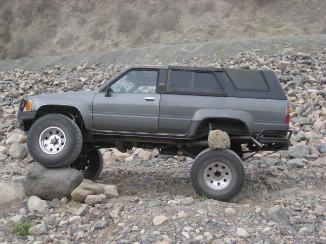
Now for the fun part, the test drive. Before I got out of my neighborhood I could tell things were much more stable. Then on the paved section through O’Neal Park the sweeper turns felt solid and the body roll was predictable. It no longer felt like I was sitting on of those playground ridding toys mounted on a coil spring where you can’t stay balanced on center but your either leaning left or right. It’s hard to believe I was cruising along on lifted rig with 5" suspension & 1" body on 35s tires! At the river crossing I turned onto the dirt road and headed up Holy Jim canyon. There really isn't any place to off road anymore but my RTI rock stack was still there. I had little effort positioning my front wheel atop of the rock so I know it must be getting some extra travel and it felt more stable.

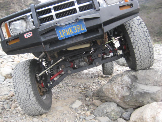
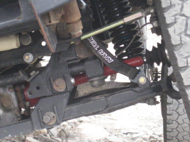
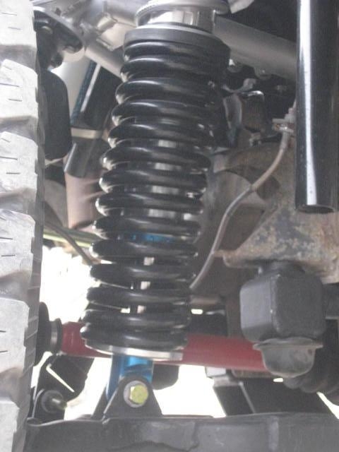
As you can see it’s still not hitting the bump stops but it’s getting a little more Up travel

In this next photo you can see the spring has more space between the coils. I count about 12 spaces of 1/4" which should give about 3" more compression before coil bind. The distance to the bump stop looks to be about 1" As for bump stop compression I give it another 1", so that adds up to 2 inches. And there also needs to be a ratio adjustment between the (LCA pivot distance to the bump) and the (LCA pivot to the shock mount) as its not 1 to 1. My estimated guess is its okay.
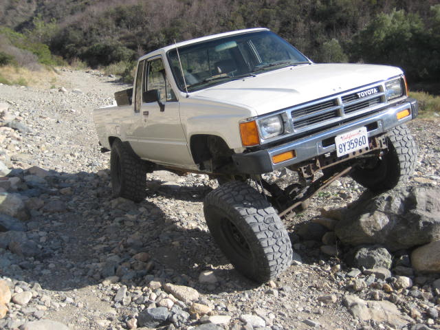
After I took the above photos I realized the driver rear tire was off the ground by about 1 inch. I weighted it down with a big rock so that it teetered and touched the ground. Then I went around front and pulled down on the driver front side of the bumper. I was able to get the LCA to just about touch the bump stop. Then I realized I was alone and had no one to take a picture. I know the bump stops are contacting the LCAs when I pre-run and I suspect they will hit in some crawl situations just not here. It’s kind of sketchy crawling in and out of the rig when it’s all crossed up, especially with a poor performing parking brake. People have been run over by their own rig and been killed doing this. Next time I am bringing a spotter.
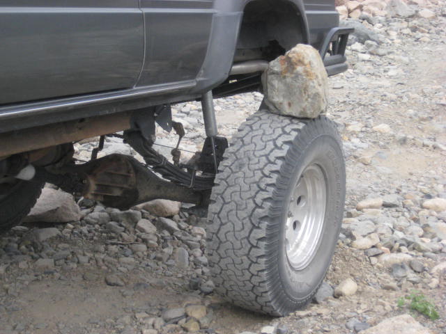
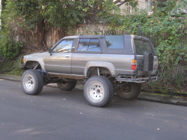
Next topic is the rear suspension. The past couple of pre-run trips I removed the mud flaps and brackets as I knew they were rubbing. There were a couple of times I would here tire rub but wasn't able to track down where. The RTI rock gave me the answer.

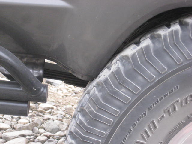
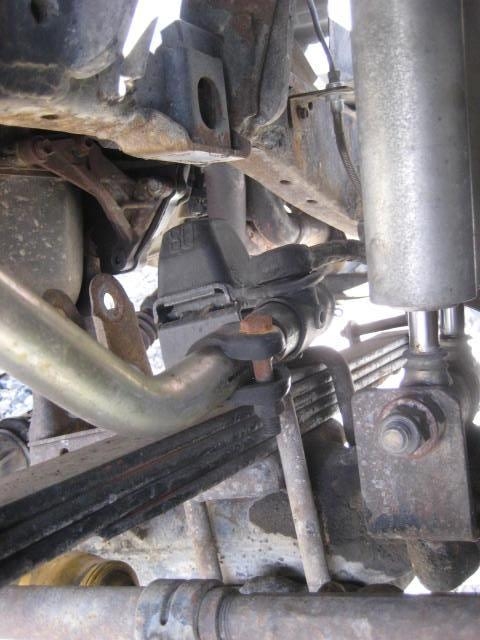
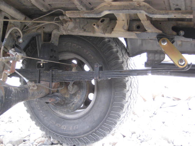
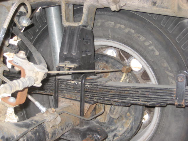
As the leaf spring moves up and down it also moves front to back and side to side. The front to back movement is obvious if you consider what the shackle is doing. When I received my leaf springs from All-Pro there were no instructions. I did some on-line searching and found very little information. Long story short I should have moved the front hanger forward 3/4" Now I get to cut it off and do it again. Bummer! Notice how I didn't cut off the old spring hangers. The new spring is just barely hitting the old hanger. I could bend the old hangers out slightly and it would clear. I'm actually glad now I didn't cut off the old hangers. I am going to use them as a reference guide to relocate the new hangers now.

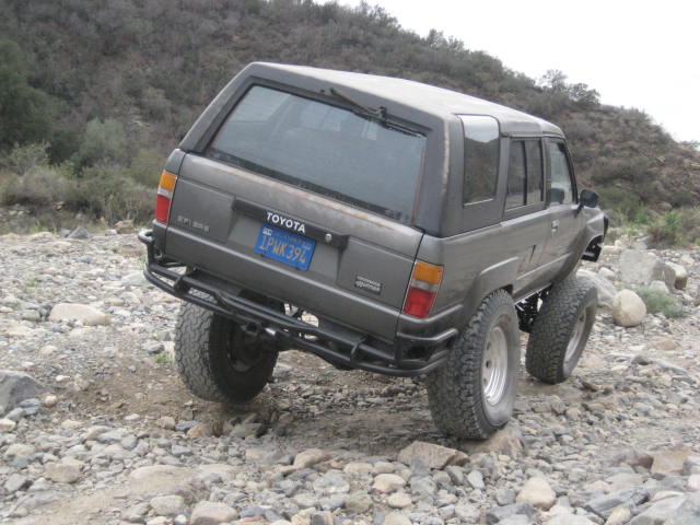
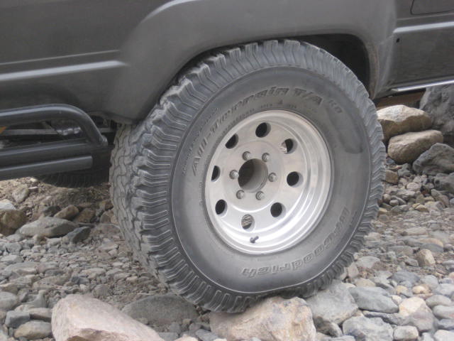
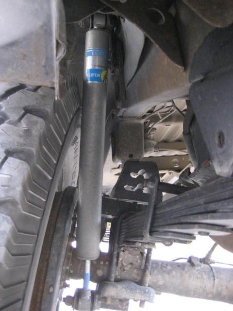
Here are a couple of photos of the rear shocks. Now you can see how much side to side movement is happening with the rear spring. This is a 2.0 diameter shock. See how the tire is almost contacting the shock at compression. Also note the bump stop alignment with the bump stop frame bracket. At droop the shock is hitting the frame. This is a 14" travel shock. Too bad I didn't have a tape measure with me. It looks like I got about 2" of shaft still showing at Up Travel, I can’t tell at all on the droop?
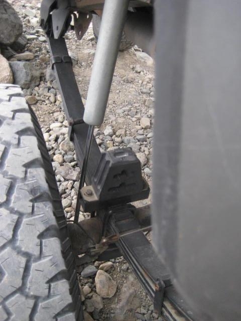
Here is a good one to see if the spring is going into negative arch, looks fairly flat to me. Of course this condition is just gently resting on the bump stop imagine what’s going on in the whoops or landing a jump or big hit. These bump stops are supposed to compress 2" so what I mentioned above about the shock shaft showing at up travel just got used up. You can also see the bump stop isn't aligned squarely on the frame bracket. More evidence I could move the front hangers forward a little bit.
Here is a photo of the C.L. springs next to the ones I had. I'm not sure why the new Kings were powder coated black? The silver 4" 500lb Eibach tender springs and black spring dividers are something I had from a previous set up on another ride.
Today I swapped out the springs. The new set up used the 18" spring in single rate and the 4" spring for tender. I installed the main spring and hand tightened the secondary lock out nuts against the spring divider with no pre-load. I was surprised when I lowered the rig and applied weight on the spring that the ride height was actually 1" higher on the passenger side and 1-1/2" higher on the driver side than before. Great, now the front is level with the rear. I then added 1/4" pre-load to the passenger side to sit level from side to side. Next I added 1/2" pre-load to the spring collar to snug the tender spring.
Now for the fun part, the test drive. Before I got out of my neighborhood I could tell things were much more stable. Then on the paved section through O’Neal Park the sweeper turns felt solid and the body roll was predictable. It no longer felt like I was sitting on of those playground ridding toys mounted on a coil spring where you can’t stay balanced on center but your either leaning left or right. It’s hard to believe I was cruising along on lifted rig with 5" suspension & 1" body on 35s tires! At the river crossing I turned onto the dirt road and headed up Holy Jim canyon. There really isn't any place to off road anymore but my RTI rock stack was still there. I had little effort positioning my front wheel atop of the rock so I know it must be getting some extra travel and it felt more stable.
As you can see it’s still not hitting the bump stops but it’s getting a little more Up travel
In this next photo you can see the spring has more space between the coils. I count about 12 spaces of 1/4" which should give about 3" more compression before coil bind. The distance to the bump stop looks to be about 1" As for bump stop compression I give it another 1", so that adds up to 2 inches. And there also needs to be a ratio adjustment between the (LCA pivot distance to the bump) and the (LCA pivot to the shock mount) as its not 1 to 1. My estimated guess is its okay.
After I took the above photos I realized the driver rear tire was off the ground by about 1 inch. I weighted it down with a big rock so that it teetered and touched the ground. Then I went around front and pulled down on the driver front side of the bumper. I was able to get the LCA to just about touch the bump stop. Then I realized I was alone and had no one to take a picture. I know the bump stops are contacting the LCAs when I pre-run and I suspect they will hit in some crawl situations just not here. It’s kind of sketchy crawling in and out of the rig when it’s all crossed up, especially with a poor performing parking brake. People have been run over by their own rig and been killed doing this. Next time I am bringing a spotter.
Next topic is the rear suspension. The past couple of pre-run trips I removed the mud flaps and brackets as I knew they were rubbing. There were a couple of times I would here tire rub but wasn't able to track down where. The RTI rock gave me the answer.
As the leaf spring moves up and down it also moves front to back and side to side. The front to back movement is obvious if you consider what the shackle is doing. When I received my leaf springs from All-Pro there were no instructions. I did some on-line searching and found very little information. Long story short I should have moved the front hanger forward 3/4" Now I get to cut it off and do it again. Bummer! Notice how I didn't cut off the old spring hangers. The new spring is just barely hitting the old hanger. I could bend the old hangers out slightly and it would clear. I'm actually glad now I didn't cut off the old hangers. I am going to use them as a reference guide to relocate the new hangers now.
Here are a couple of photos of the rear shocks. Now you can see how much side to side movement is happening with the rear spring. This is a 2.0 diameter shock. See how the tire is almost contacting the shock at compression. Also note the bump stop alignment with the bump stop frame bracket. At droop the shock is hitting the frame. This is a 14" travel shock. Too bad I didn't have a tape measure with me. It looks like I got about 2" of shaft still showing at Up Travel, I can’t tell at all on the droop?
Here is a good one to see if the spring is going into negative arch, looks fairly flat to me. Of course this condition is just gently resting on the bump stop imagine what’s going on in the whoops or landing a jump or big hit. These bump stops are supposed to compress 2" so what I mentioned above about the shock shaft showing at up travel just got used up. You can also see the bump stop isn't aligned squarely on the frame bracket. More evidence I could move the front hangers forward a little bit.
Last edited by BlazeN8; 01-27-2014 at 09:37 AM.
01-27-2014, 04:26 PM
#354
Registered User
thanks for posting flex pics, suprised there is enough room for shocks at full flex.
I'm curious how you layed out the front spring mount location.
plumb bob from the center of the bump stop bracket to the center of the axle?
my plans for the rear suspension on my truck include a T100 axle which iirc is eight inches wider than my stock axle, which should give me enough room for a triple bypass shock outside the frame rail with air bumps.
the shock going through the bed on the side with a front half cage around the sides and front of the bed to leave as much room in the bed.
a set of deavers with a spring under axle kit should allow sixteen to eighteen inches of travel. should be more than enough to keep up with whatever front kit i go with.
my question is with the additional travel of my planned setup would i have enough room at full flex to avoid interference issues?
Last edited by donomite49; 01-27-2014 at 04:27 PM.
01-27-2014, 11:33 PM
#356
Registered User
Thread Starter
Thanks RW and Korn!
Donomite, when I laid out my spring hangers I read about the particulars of this application someplace but don't remember where. I took the information I had read about as a guide but didn't follow word for word. I do remember dropping a plumb line from the center of the bump stop frame bracket. From there I measured forward the distance I measured on the spring from the center bolt to the front eye. I think my mistake might have been I didn't compensate for the flattening of the arch. I was only off 1/2-3/4" to have the wheel centered at full stuff. I'm not even sure its worth re-locating the front hanger as the tire is also hitting the top and center of the fender. For now I am just going to shim the bump stop frame bracket. This is something that I had done earlier in this build thread so its just a matter of dusting off the shims and reinstalling them.
In case it was missed or I never stated I do have 3" wheel adapters in the rear. Kind of a cheesy way of widening the rear axle but its been working fine on both my truck and 4 Runner for years. Donomite, if you end up going with the T-100 axle and its added width is what you mentioned, a 2.5 tripple bypass may work? You'll have to confirm that on your own!
As far as the travel numbers I am getting from the 6" All-Pro I have not measured it out. My guesstimate is its close to 14" with full bump stop compression? I should take some droop measurements and figure it out. I need to make sure I am not asking my shock to be a limit strap. The shock angle of my 14" Billy's is not very great so its close to a 1 to 1 ration.