
Philbert's 87 4Runner Head Gasket & head replacement - take II

 03-31-2013, 06:40 PM
#162
Registered User
Thread Starter
iTrader: (2)
Join Date: Dec 2009
Location: Pleasanton, CA - SF Bay Area
Posts: 2,159
Likes: 0
Received 7 Likes
on
5 Posts
Does the second pic in post 58 jog any memories on that coolant hose?
That is exactly what I needed, THANK YOU! I actually have been following this thread so now I really feel dumb

I have the old hose (didn't buy a new one, and it's in pretty good shape).
Now I can move on!
More pics to come...it's opening day for the Oakland A's tomorrow so I won't get a thing done tomorrow I know
Thanks guys for the kick in the pants!
 03-31-2013, 10:24 PM
#165
Registered User
Thread Starter
iTrader: (2)
Join Date: Dec 2009
Location: Pleasanton, CA - SF Bay Area
Posts: 2,159
Likes: 0
Received 7 Likes
on
5 Posts
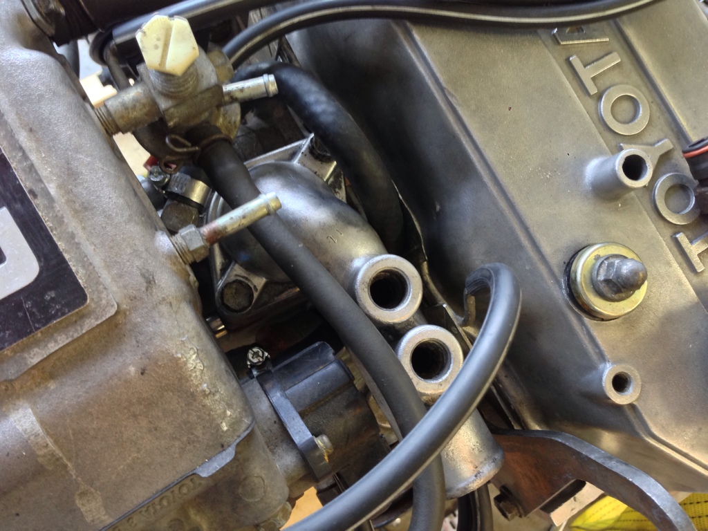
Yeah, I took a photo after I mocked it up tonight - hard to see with the shadows, but the hose connects the two mystery ports in question:

Thanks a ton - this will make the rest a LOT easier, as I was hung up on this for some time.
The other thing that's slowing me down is my crappy radio shack soldering iron can't handle the 10 gauge alternator harness wire I'm trying to piggyback onto for my GM alternator :/ Any tips?
Thanks a ton - this will make the rest a LOT easier, as I was hung up on this for some time.
The other thing that's slowing me down is my crappy radio shack soldering iron can't handle the 10 gauge alternator harness wire I'm trying to piggyback onto for my GM alternator :/ Any tips?
03-31-2013, 10:55 PM
#166
Got flux? If so used it it'll help the heat transfer better. If you don't have flux try a glob of solder on the tip of the iron, this also helps the heat transfer better. In a pinch you can use plumpers flux for copper pipes, it's a pain to clean up but meh.
LOL so ingrained not to touch the tip of a soldering iron I just spazzed out when I droped it in my lap. Hasn't been used in weeks, just gut reaction..
LOL so ingrained not to touch the tip of a soldering iron I just spazzed out when I droped it in my lap. Hasn't been used in weeks, just gut reaction..
03-31-2013, 11:13 PM
#167
http://www.youtube.com/watch?v=Vh9pW...mbedded#t=176s
Drated preview button I swear it moves
PS. here is the page link for that video, more reading material..
I Use a chisel tip for just about everything, it's just a conical tipthats been filed down it'll reduce the life span some if you go thru the sheathing but meh it's a radioshack tip they're plenty cheap.
Last edited by Co_94_PU; 03-31-2013 at 11:17 PM.
04-07-2013, 10:53 PM
#168
Registered User
Thread Starter
iTrader: (2)
Join Date: Dec 2009
Location: Pleasanton, CA - SF Bay Area
Posts: 2,159
Likes: 0
Received 7 Likes
on
5 Posts
Progress!
Well, got a fair amount done this weekend - my old thread still does not work on the last page so I'll continue to update this one....
Installed intake manifold, A/C and power steering hardware, alternator, wiring harness (hooked it all up), and did the wiring (swapped ground wire to drivers side, ran 4 gauge from alternator to drivers side, ran new 10 gauge wire from fuse box to drivers side where battery will be, and extended AFM OEM wiring harness for Supra AFM on passenger side).
The alternator adjustment bracket was a sonofabitch! It's the trail gear kit and I had the hardest time getting the bolt (that threads into the alt to tighten it on the adjuster rail) to fit through. I ended up taking my wangle grinder to it to widen the gap along the adjuster rail - looks terrible but I think will work (there wasn't a lot of play in the alt anyway....).
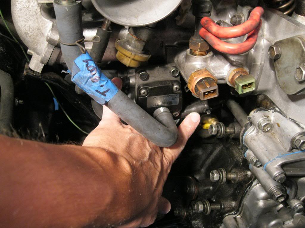
Here's that crazy hose I couldn't figure out earlier, which loops around the T stat housing...turns out I *did* order a new one after all - which I'm happy about:

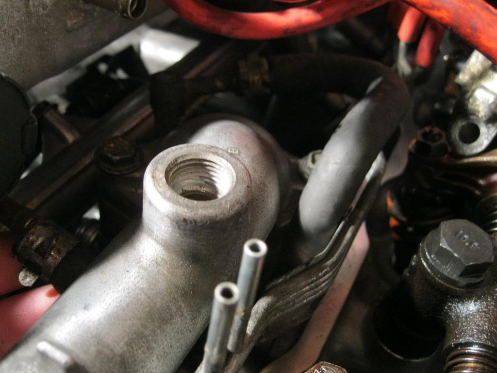
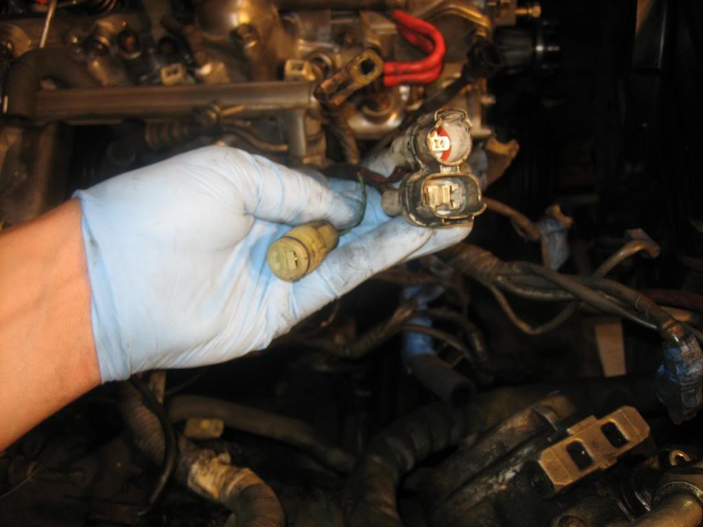
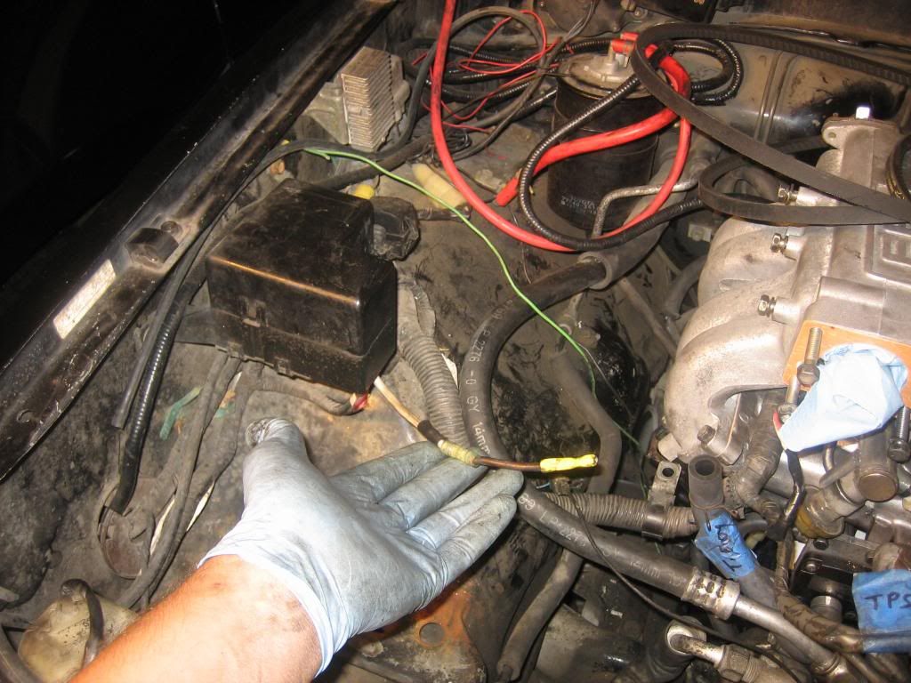
these 2 senders (green and brown) are pretty loose where the plugs hook up - not sure if they still work but we'll see:
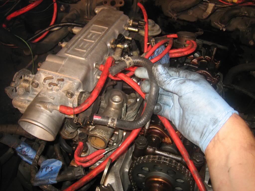
When hooking everything up, I noticed this white plug on the right in the photo, has 2 female plugs, but only ONE male (from the transmission) plugs in....is the other female plug for an automatic maybe?
I seem to have misplaced the bolt that holds the black support to the intake manifold (foreground, in front of my blue glove):
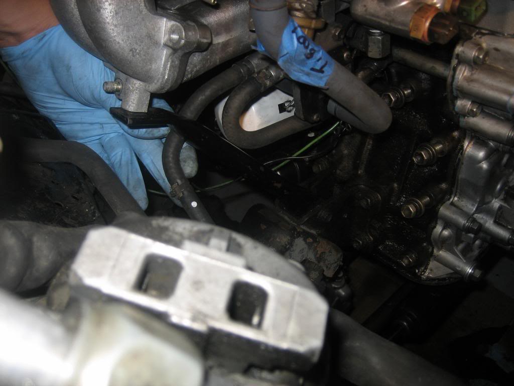
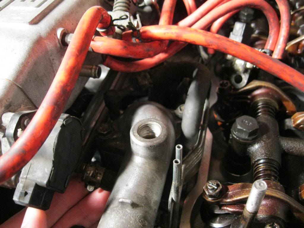
I also can't find the bolt for the cold start injector (I know I had it....it's a special bolt that works with the banjo style fitting):
My 4 gauge cable from the new GM alternator to + battery - with 150A fuse in-line where it connects to + on battery:
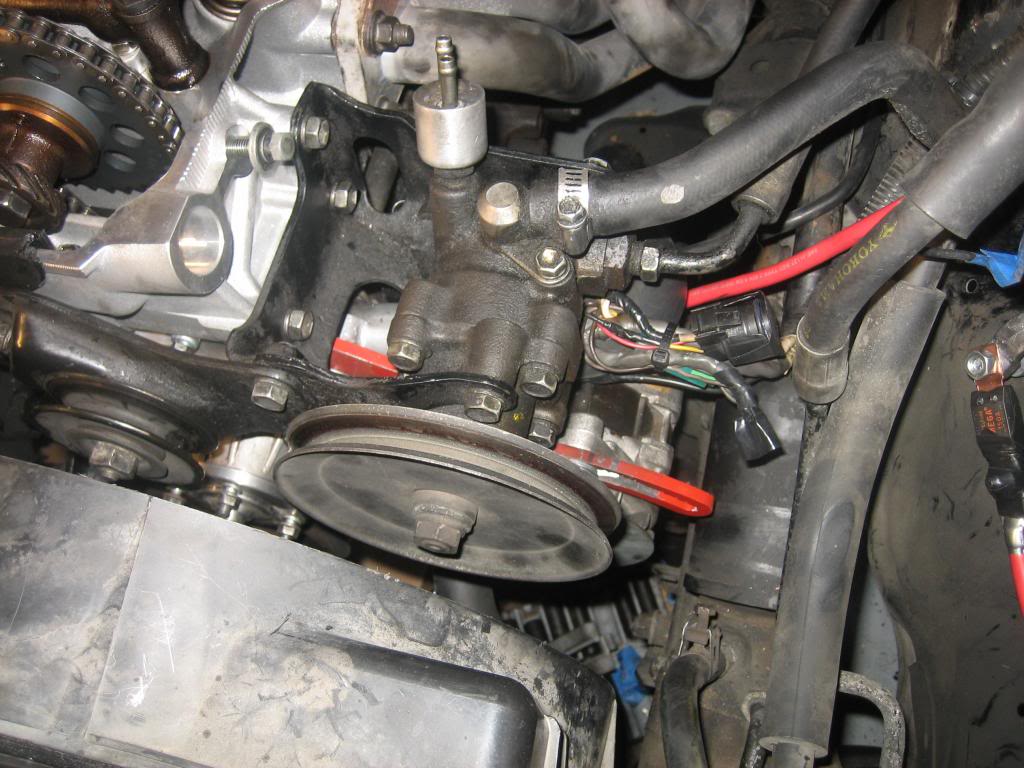
Power steering pump and bracket installed - note the "old" alternator wiring tucked out of the way with zip ties:
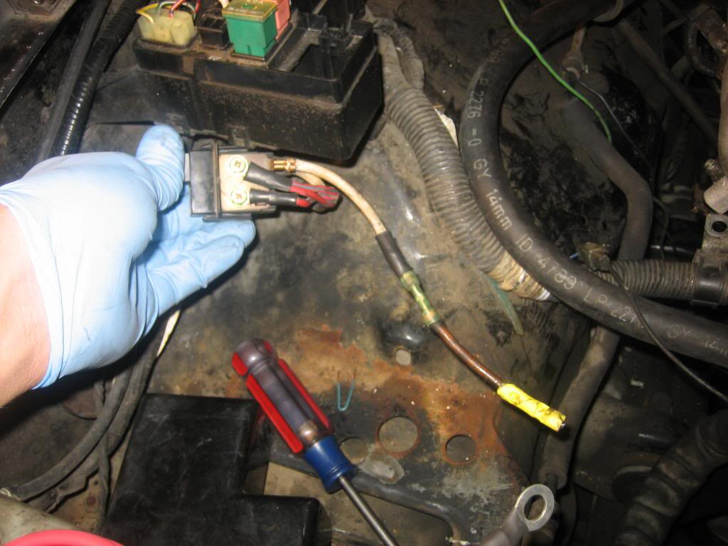
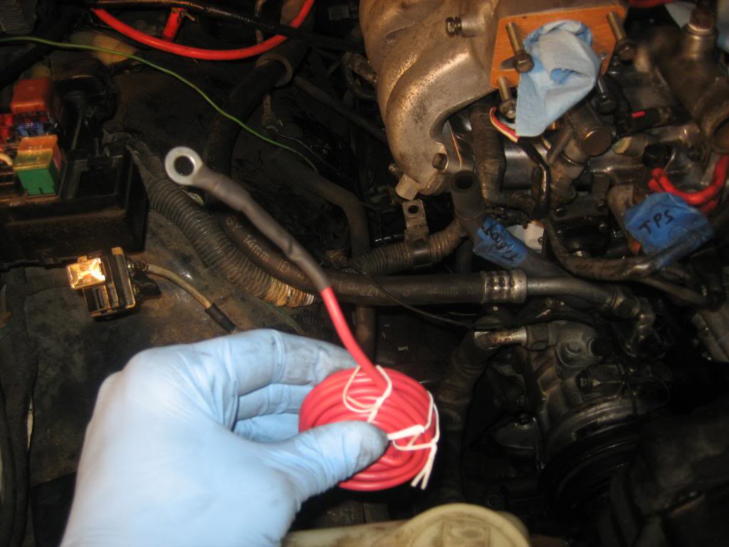
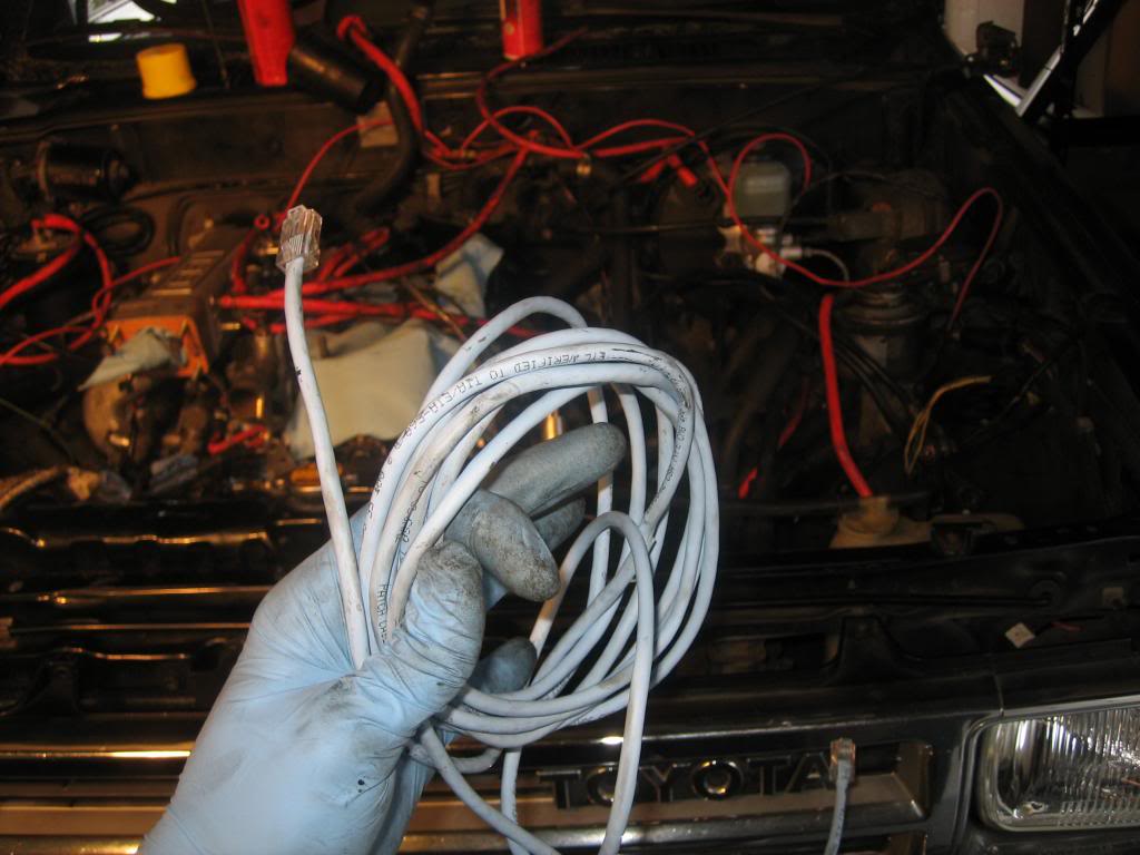
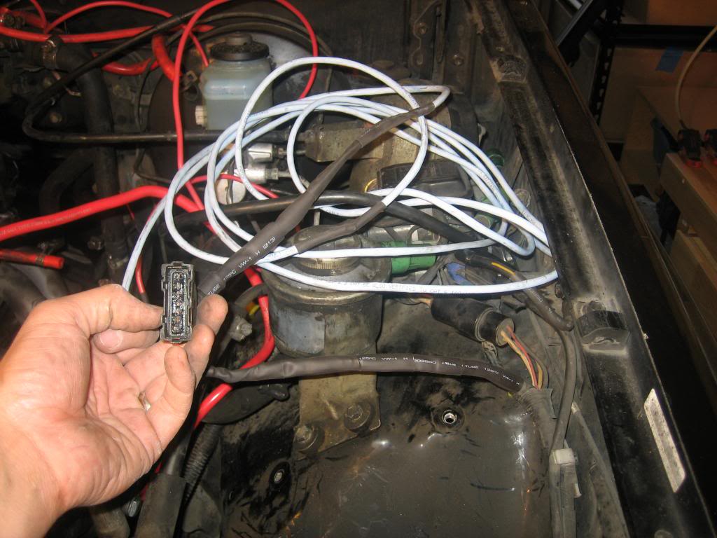
Here's the old charge wire from the fuse box to the + battery - I think it had 3-4 butt connectors in-line (!):

New 10 gauge wire hooked up with eye ring terminal, crimped soldered, heat shrinked;
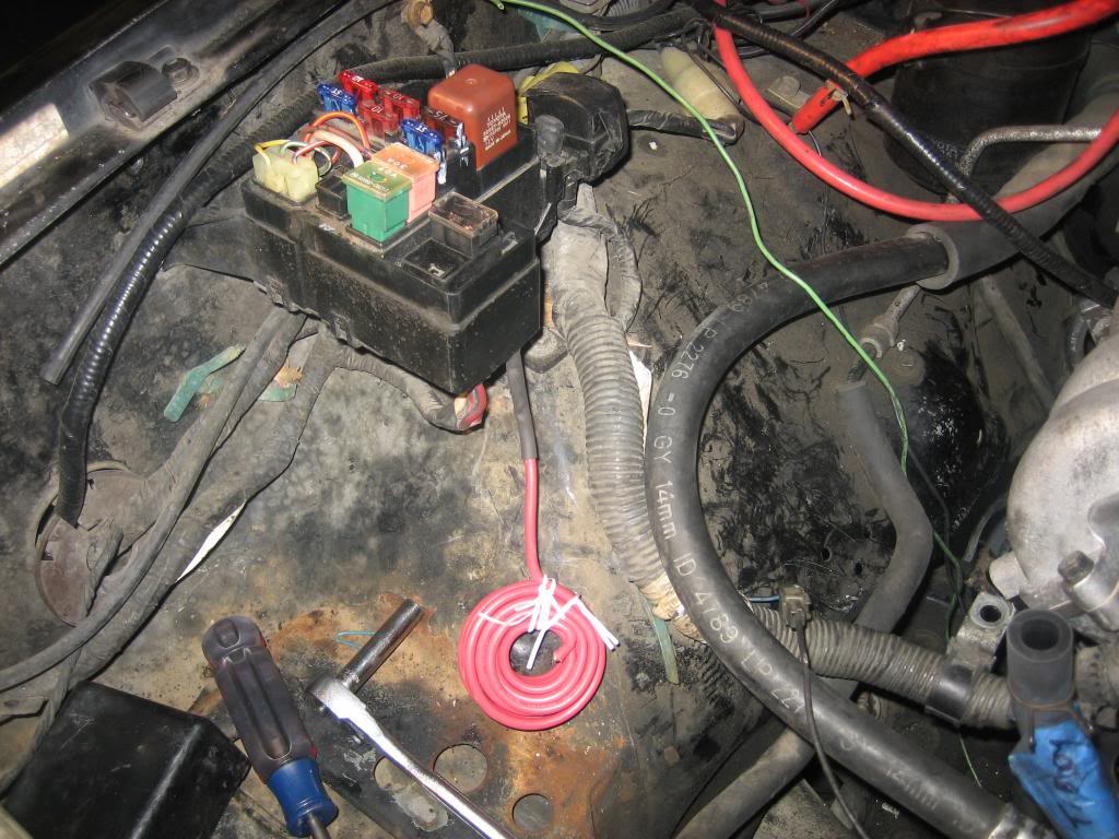
And installed in fuse box:
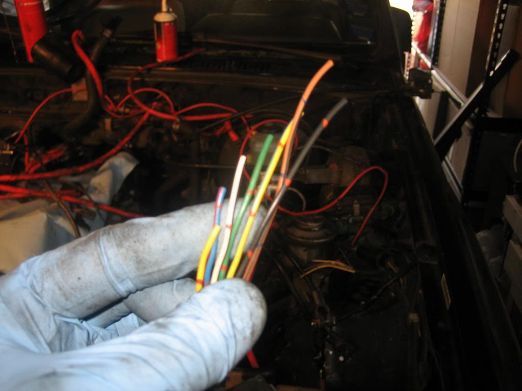
The OEM AFM wiring harness:
And my extender cable - CAT5:
(I need 7 wires, it has 8 insulated wires, in its own sheath)
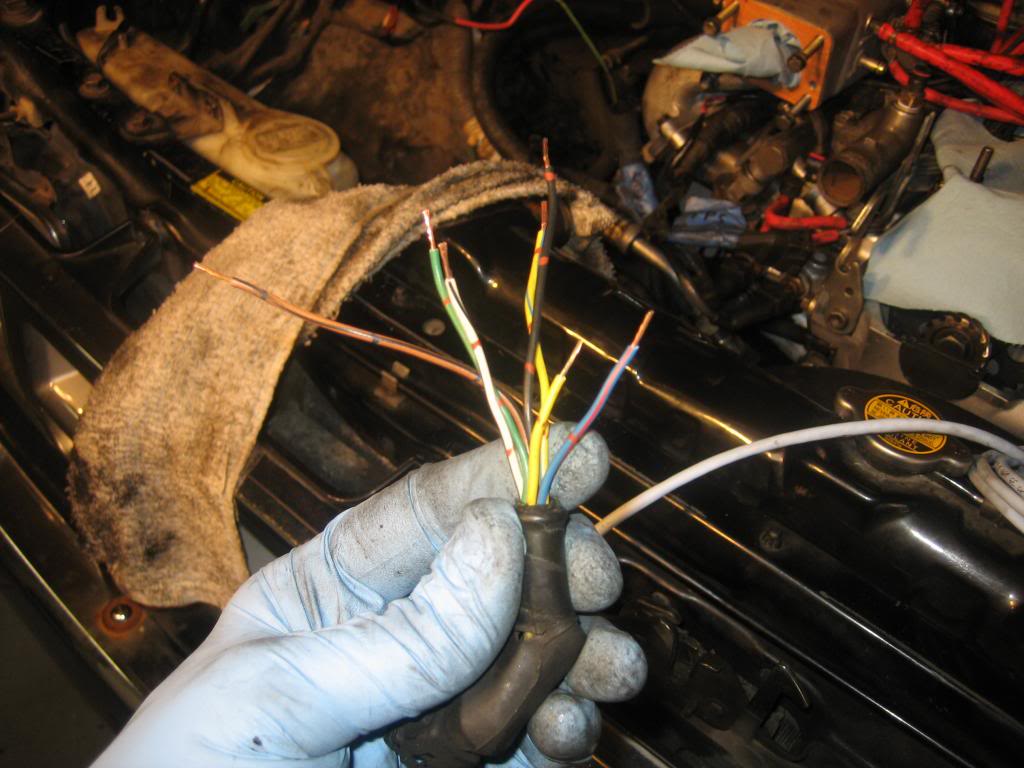
I cut each of the OEM wires about 1/4" shorter than the next one:
Then took off another 1/4" of insulation:
Then did the same on the CAT5 wiring, and soldered them up with heat shrink:
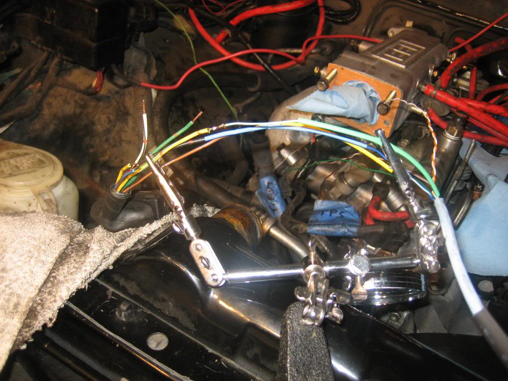
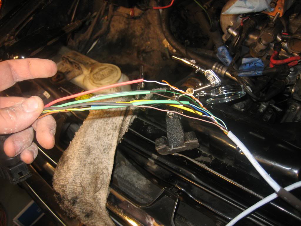
the plug, with heat shrink to cover it all up:
How it ended up looking:
I have everything installed except I need to:
- adjust TPS (removed from truck, will use multimeter and Roger's guide)
- Install Distributor
- Find/install fuel line bolt and new crush washer
- Install Supra AFM (thanks Kiyobrown)
- Install battery (still need to figure out how to mount it....)
- Find longer Alternator belt to match up to the GM one....
- Button it up and route vacuum hoses
- Install spark plugs
- torque crank pulley
- install fan clutch, belts
Once all that's done, I will crank it a few times with oil in it (coil unplugged, to get oil circulated without starting)...then hook it up and do the cam break in, timing, valves.
I torqued the head bolts to 58 ft/lbs, per FSM....I know some have said to torque them to 63....these are new head bolts and a new ENGNBLDR head - what do you guys think? Guy at NAPA, who has owned his 86 22RE since 87, told me he's heard that but always torqued to spec (58). He's done 2 HG jobs himself....
Also, he recommended adding stop leak into the water the first time I fire it up, just as a precaution on the HG - any objections?
Anything I'm not thinking of, missing???
Thanks for following!
Phil
Installed intake manifold, A/C and power steering hardware, alternator, wiring harness (hooked it all up), and did the wiring (swapped ground wire to drivers side, ran 4 gauge from alternator to drivers side, ran new 10 gauge wire from fuse box to drivers side where battery will be, and extended AFM OEM wiring harness for Supra AFM on passenger side).
The alternator adjustment bracket was a sonofabitch! It's the trail gear kit and I had the hardest time getting the bolt (that threads into the alt to tighten it on the adjuster rail) to fit through. I ended up taking my wangle grinder to it to widen the gap along the adjuster rail - looks terrible but I think will work (there wasn't a lot of play in the alt anyway....).
Here's that crazy hose I couldn't figure out earlier, which loops around the T stat housing...turns out I *did* order a new one after all - which I'm happy about:
these 2 senders (green and brown) are pretty loose where the plugs hook up - not sure if they still work but we'll see:
When hooking everything up, I noticed this white plug on the right in the photo, has 2 female plugs, but only ONE male (from the transmission) plugs in....is the other female plug for an automatic maybe?
I seem to have misplaced the bolt that holds the black support to the intake manifold (foreground, in front of my blue glove):
I also can't find the bolt for the cold start injector (I know I had it....it's a special bolt that works with the banjo style fitting):
My 4 gauge cable from the new GM alternator to + battery - with 150A fuse in-line where it connects to + on battery:
Power steering pump and bracket installed - note the "old" alternator wiring tucked out of the way with zip ties:
Here's the old charge wire from the fuse box to the + battery - I think it had 3-4 butt connectors in-line (!):
New 10 gauge wire hooked up with eye ring terminal, crimped soldered, heat shrinked;
And installed in fuse box:
The OEM AFM wiring harness:
And my extender cable - CAT5:
(I need 7 wires, it has 8 insulated wires, in its own sheath)
I cut each of the OEM wires about 1/4" shorter than the next one:
Then took off another 1/4" of insulation:
Then did the same on the CAT5 wiring, and soldered them up with heat shrink:
the plug, with heat shrink to cover it all up:
How it ended up looking:
I have everything installed except I need to:
- adjust TPS (removed from truck, will use multimeter and Roger's guide)
- Install Distributor
- Find/install fuel line bolt and new crush washer
- Install Supra AFM (thanks Kiyobrown)
- Install battery (still need to figure out how to mount it....)
- Find longer Alternator belt to match up to the GM one....
- Button it up and route vacuum hoses
- Install spark plugs
- torque crank pulley
- install fan clutch, belts
Once all that's done, I will crank it a few times with oil in it (coil unplugged, to get oil circulated without starting)...then hook it up and do the cam break in, timing, valves.
I torqued the head bolts to 58 ft/lbs, per FSM....I know some have said to torque them to 63....these are new head bolts and a new ENGNBLDR head - what do you guys think? Guy at NAPA, who has owned his 86 22RE since 87, told me he's heard that but always torqued to spec (58). He's done 2 HG jobs himself....
Also, he recommended adding stop leak into the water the first time I fire it up, just as a precaution on the HG - any objections?
Anything I'm not thinking of, missing???
Thanks for following!
Phil
04-08-2013, 06:26 AM
#169
Registered User

Join Date: Sep 2007
Location: San Francisco East Bay
Posts: 8,299
Likes: 0
Received 841 Likes
on
661 Posts
..., ran new 10 gauge wire from fuse box to drivers side where battery will be,
Here's the old charge wire from the fuse box to the + battery - I think it had 3-4 butt connectors in-line (!):
New 10 gauge wire hooked up with eye ring terminal, crimped soldered, heat shrinked;
And installed in fuse box:

Here's the old charge wire from the fuse box to the + battery - I think it had 3-4 butt connectors in-line (!):
New 10 gauge wire hooked up with eye ring terminal, crimped soldered, heat shrinked;
And installed in fuse box:
04-08-2013, 07:16 AM
#170
Registered User
Thread Starter
iTrader: (2)
Join Date: Dec 2009
Location: Pleasanton, CA - SF Bay Area
Posts: 2,159
Likes: 0
Received 7 Likes
on
5 Posts
Thanks Scope - and I think you're right - that is the fusible link (along with some connectors from over the years).
I should replace it (I know there is a fuse in the fuse box that it leads to (in photos) but I should still have a fusible link before the power reached the fuse box).
That said, do you (or anyone else following) know what to ask for at the auto parts store when I get a replacement? And it should be mounted as close to the fuse box as possible, not the battery, correct? I've done fuses before but never a fusible link....
As far as electrical, here's what I did for grounds/etc:
- Starter wire (4 gauge) to + on battery
- 10 gauge wire from + on battery to fuse box (what Scope says I should add a fusible link to)
- Charge wire (4 gauge) from alt to + on battery (with 150A fuse in-line where it attaches to + on battery)
- Ground wire (4 gauge) from - on battery to block (moved from pass side to drivers side (used same OEM bolt and found an unused block threaded hole)
- - on battery to body (used existing OEM wire (14 gauge?) and a bolt that was already there
- Ground: head to body (used existing OEM wiring (14 gauge?)
- Ground: intake manifold to wiring harness (OEM wiring)
- Ground: alternator harness to block (OEM wiring)
Anything else I'm missing?
Comments on torquing the head bolts?
Thanks
04-08-2013, 09:35 AM
#171
Registered User
Join Date: Sep 2007
Location: San Francisco East Bay
Posts: 8,299
Likes: 0
Received 841 Likes
on
661 Posts
I think what you want is the "Fusible Link Repair" http://www.toyotapartszone.com/Page_...onentsID=82-02 Unfortunately, the Toyota part is no longer available. Some of the other parts called "fusible link" are what we know as the 80 and 40 amp fuses, so are not what you want.
Someone probably makes "raw" fusible link cable, which could be crimped (real crimps; not the insulated blue and red "crushable" ones from the hardware store) into the power cable. I can't tell you what mine looks like; it's neatly wrapped in tape so I can't see it.
Are you sure the old cable should be replaced? The butt connectors look like the ones I think are supposed to be there. But I don't know about the rest of the connectors on the ends of your cable.
I'm sure you're proud of your new red cable, but you don't want to be the guy who "improved" his house wiring by replacing the dusty old 15amp circuit breakers with nice, clean "better" 20amp breakers.
And yes, just like a circuit breaker, the fusible link goes as close to the battery as you can get it. Otherwise, the wire from the battery TO the fusible link is not protected.
Edit: Here's a step-by-step on our very own forum: https://www.yotatech.com/forums/f116...cement-228307/
(including the inevitable "I don't need fuses, so I just replaced it with a giant piece of wire" comment.)
Last edited by scope103; 04-08-2013 at 09:42 AM.
04-08-2013, 10:28 AM
#172
Registered User
Thread Starter
iTrader: (2)
Join Date: Dec 2009
Location: Pleasanton, CA - SF Bay Area
Posts: 2,159
Likes: 0
Received 7 Likes
on
5 Posts
Thanks Scope for the reference - I just read that entire post, though I'm not sure it fully answers the question of "do a I need the FL since I have an 80A fuse in the box the wire leads to"?
The wire I had was pretty beat up and had so many butt splices, I didn't feel comfortable with it - that's why I'm replacing it....also because of the battery swap, it made sense to lengthen it to reach the fuse box.
Looking at the part description you linked to, it says for a 60A alternator (stock)....well, I upgraded to 120, so wouldn't I need an upgraded slow blow/FL that could handle 120A?
I'm by no means an electrical expert and I can tell you know a lot more than me already - I just don't want to skip an important step here, and want to understand it fully.
I did blow that OEM 80A fuse a couple years ago when I reverse jumped my truck in the dark, in the rain (yes, we all have had a moment like that, or if not, will...). Luckily, that fuse saved my entire electrical system, so I can appreciate a fuse in the right spot - just want to understand it better first.
That said, do you think an in line fuse, close the + as possible, on my 10 gauge wire, rated at, say 130A would suffice? Now I'm confused even more because I have a 120A alternator (replacing a stock 60A alternator), and the stock fuse that the battery wire goes to is only 80A....but does the entire system just draw as much amperage is it needs, based on what's being used - and the alternator just provides enough "on tap" as needed, not necessarily running 120A through the system all the time?
Thanks
04-08-2013, 11:18 AM
#173
Registered User
Join Date: Sep 2007
Location: San Francisco East Bay
Posts: 8,299
Likes: 0
Received 841 Likes
on
661 Posts
I have to admit that I haven't gone through all of this, but you raise some interesting questions.
A car/truck battery can usually put out more than 130amps ("Cold Cranking Amps" or CCA on the battery label) into a near-dead-short (the starter), but only for a few seconds. After the truck starts, the alternator starts re-charging the battery, through the 80amp fuse. Usually, the battery hasn't been discharged that far and has at least 12volts; 14.1volts from the alternator is just pushing 1.9volts against the internal resistance of the battery. So probably something like 10 amps or so for a few minutes. Once the battery is charged up the current through the 80amp fuse is probably less than 1amp, as the headlights and such are being powered from the alternator. (which bypasses the 80amp fuse in that case)
But what if the battery is very nearly dead? If it can put out 130 amps when charged, could it's internal resistance be so low that when 14.1v charging voltage is put on it, it would charge at 100amps? Usually, we don't worry about that because the 60amp alternator can't put out that much, so the 80amp fuse is plenty. But what if you put in a 120amp alternator? Wouldn't that require a larger fuse than 80amps? And if you increase the size of that fuse, don't you need to increase the size of every conductor and every switch and every relay that connects to it?
I think the answer is that you can get away with a 120amp alternator as long as you never let the battery get too far discharged. But if you do, it could blow the 80amp fuse, and then you can't charge the battery!
[All that being said, why DID you put in an over-sized alternator? Usually, this is for those who want to run a christmas tree worth of off-road lights AND a buzzybox sub-woofer AND a refrigerator all with the engine idling.]
If you get an inline fuse of some sort, it would have to be built-in to the cable. No spring-loaded fuse holder could ever handle 80amps. But within the last three weeks someone posted a picture of replacement cable with an integral circuit interrupter on this forum.
Incidentally, for household wiring the electrical code limits the use of 10ga wire to 30amps. There are multiple reasons why the electrical code comes out there, so you could probably hit 55 amps in 10ga, as long as it was able to dissipate heat (as in, not bundled up with other cables, or run through some sort of conduit.) As I mentioned before, you would rarely see as much 30amps on the battery wire, even with a 60amp alternator.
Last but not least, I believe I once read that a fusible link was not only to protect against over-currents, but fire itself, so that the link would open when exposed to excessive heat even if the current alone wouldn't do it. So if you have an engine compartment fire it will turn off the power for you.
So I don't really have an answer for you, and would be interested to hear from someone who knows more than I do. (and in case you haven't guessed, the "I replaced the battery wire with a piece of coat hanger 6 weeks ago and I'm not dead yet" kind of answer is not too helpful to me.)
04-08-2013, 11:25 AM
#174
Registered User
Thread Starter
iTrader: (2)
Join Date: Dec 2009
Location: Pleasanton, CA - SF Bay Area
Posts: 2,159
Likes: 0
Received 7 Likes
on
5 Posts

Thanks for weighing in and I, like you, will await someone with more knowledge than the both of us.
Are you thinking of RAD4RUNNER? He seems to REALLY know his electrical circuits - maybe I'll PM him now and try to steer him over to my thread....
04-08-2013, 02:49 PM
#175
Thanks for the vote of confidence. I don't think I know more than Scope103, but 3 heads know more than one does
Quick answer: I concur with Scope103's analysis, and keep the original rated fusible link
Then, I would:
- Double the wire size of white ("B") wire from alternator of alternator to where it joins the fuses,
- put a distribution point between battery and alternator, along this same thicker wire. Good location for distribution point would be inside left-hand fender, near the alternator.
- Wire your christmas tree lights - LOL - and other purely resistive/lighting loads to that (fused, of course), closer to the alternator so as not to overload your 80-am fusible link.
- Then, wire anything with electronics to battery (cleaner power) like most setups.
I think this setup would make alternator and battery share the demands safely, your stock fuses and FL's will still safely protect everything, and you have enough room on left-side for additional relays.
Last edited by RAD4Runner; 04-08-2013 at 02:52 PM.
04-08-2013, 03:40 PM
#176
Registered User
Thread Starter
iTrader: (2)
Join Date: Dec 2009
Location: Pleasanton, CA - SF Bay Area
Posts: 2,159
Likes: 0
Received 7 Likes
on
5 Posts
Thanks RAD4RUNNER for chiming in - really appreciate it
I'm not quite sure I follow all those bullet points but will keep reading them and maybe it will sink in.
Here is a crude drawing I did at work and posted in my original build thread (it disappeared, along with the last page of my thread, that's why I Started this thread...):
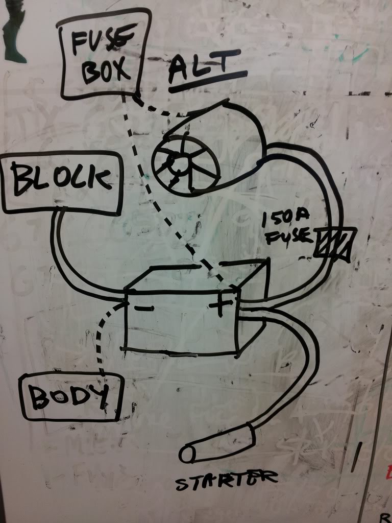
The diagram shows what I outlined in text a few posts ago:
- The "thick" wires are all 4 gauge
- the 150A fuse is in line with the wire from alt to + and is between the end of the wire and the "+" post
- The longest dashed line is the one I just replaced with 10 gauge red wire and hooked directly into the fuse box
- The short dashed line under the word "alt" is the original wire with ring terminal that hooked onto the charge post on the OEM alternator - I covered this ring terminal up with electrical tape and tucked out of the way along with the OEM Alternator plug. the drawing shows it connecting to the fuse box but I ended up not doing that after all.
Knowing all that, do you still recommend I:
- install the old fusible link (I haven't looked closely but do you think I can just strip and splice/solder into the new 10 gauge wire?)?
- do those other things in your bullet points?
As far as christmas trees....I may install some lighting later, and it sure would be nice if my windows rolled up faster Mostly, just wanted to upgrade because - just in case. No winch plans or anything crazy like that - this is my DD, but I do want to get it dirty some day.
Thanks!
I'm not quite sure I follow all those bullet points but will keep reading them and maybe it will sink in.
Here is a crude drawing I did at work and posted in my original build thread (it disappeared, along with the last page of my thread, that's why I Started this thread...):
The diagram shows what I outlined in text a few posts ago:
- The "thick" wires are all 4 gauge
- the 150A fuse is in line with the wire from alt to + and is between the end of the wire and the "+" post
- The longest dashed line is the one I just replaced with 10 gauge red wire and hooked directly into the fuse box
- The short dashed line under the word "alt" is the original wire with ring terminal that hooked onto the charge post on the OEM alternator - I covered this ring terminal up with electrical tape and tucked out of the way along with the OEM Alternator plug. the drawing shows it connecting to the fuse box but I ended up not doing that after all.
Knowing all that, do you still recommend I:
- install the old fusible link (I haven't looked closely but do you think I can just strip and splice/solder into the new 10 gauge wire?)?
- do those other things in your bullet points?
As far as christmas trees....I may install some lighting later, and it sure would be nice if my windows rolled up faster
Mostly, just wanted to upgrade because - just in case. No winch plans or anything crazy like that - this is my DD, but I do want to get it dirty some day.Thanks!
04-08-2013, 04:21 PM
#177
You want a fusible link, not a fuse, and located as close as practicle to the battery. Don't forget to replace the fiberglass sheeth, it keeps it from contacting the body, or you have the makings for a battery bomb.
Here is link, it explains nicely why a fuse doesn't do the same job as a fusible link. Basicly it says fuses fatigue, and don't handle surge load. For instance the starter is stalled when you first crank it over, he specificly mentioned an electric fan but it's the same principal, Stalled electric motor = infinate load for short time.
He also gives a thumb rule for them, 4 sizes/guage smaller than the wire you are trying to protect.
Now the alternator output..
This is limited by the regulator and engine speed. So even if the battery is flat it won't exceed a certain amp output. At idle speeds (upto 2k/rpm) the stock one is limited to only 10 amps, the one RAD' or Cyber' linked a few days ago was rated for ~40A at idle. I didn't dig up the idle rateing for a 120a GM, I feel safe assuming it's in the 1/3-1/6 of the maxium.
The fusible links in the relay block... I'm less certain about this bit.
When they use the 55A alt' the FL is a 60A, when they use the 60A alt' they upgrade to an 80A and inline a 40A one to the alternator.
I'd say buy some spares and keep them in the onboard truck repair kit. Why? Because you didn't upgrade the rest of the wiring, you only want to replace/upgrade the ones for the wires you increased the size on.
When you go to adding new accessories then you'll add a power take off wire from the battery to your new block, and add an appro' sized FL between the battery and wiring/fuse block.
You can parallel FL but they'll be slightly derated due to heat exchange between the two.
----After mashing preview to see if RAD showed up yet----
First off before I forget, you need more shrink wrap on that ALT-BAT wire (bare spots) and less over the fuse (traps in the heat, derates the fuse), and might want to replace your taped over old hoop with heatshrink for reliablility.
I like the idea of having a drivers side power/fuse block. I'd go with a Fl at the alternator and the battery on the wire runs to the new power block, 8g for your 4g wires.
I likely missed some direct questions, sorry
04-08-2013, 08:04 PM
#178
Registered User
Thread Starter
iTrader: (2)
Join Date: Dec 2009
Location: Pleasanton, CA - SF Bay Area
Posts: 2,159
Likes: 0
Received 7 Likes
on
5 Posts
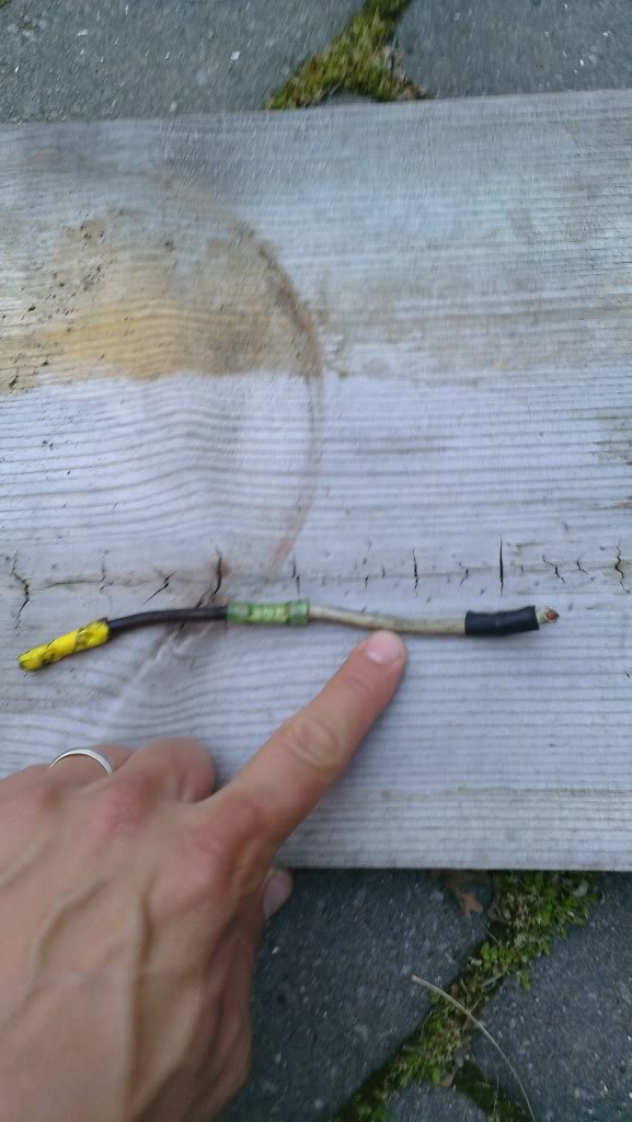
I went to the auto parts store after work and picked up some belts to try out on the new alt set up. While there I asked about fusible links and they pointed me toward some spools of thicker gauge wire, all labeled "Fusible links"....for some reason I thought they'd be shorter, specialized pieces of wire...is this normal?
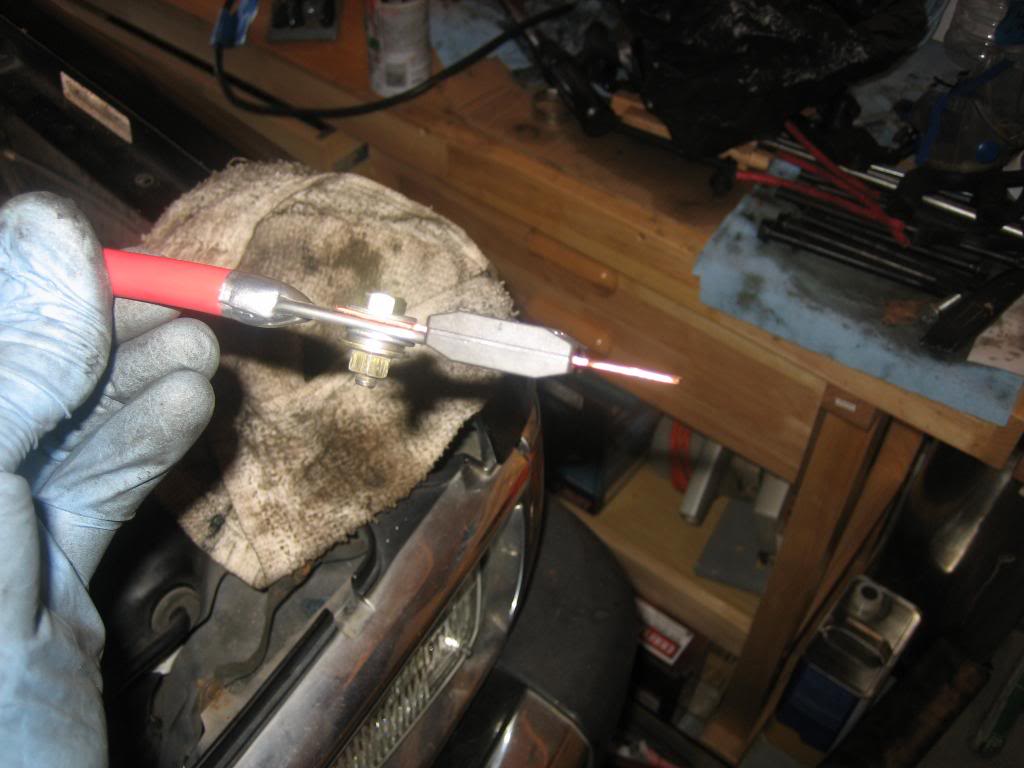
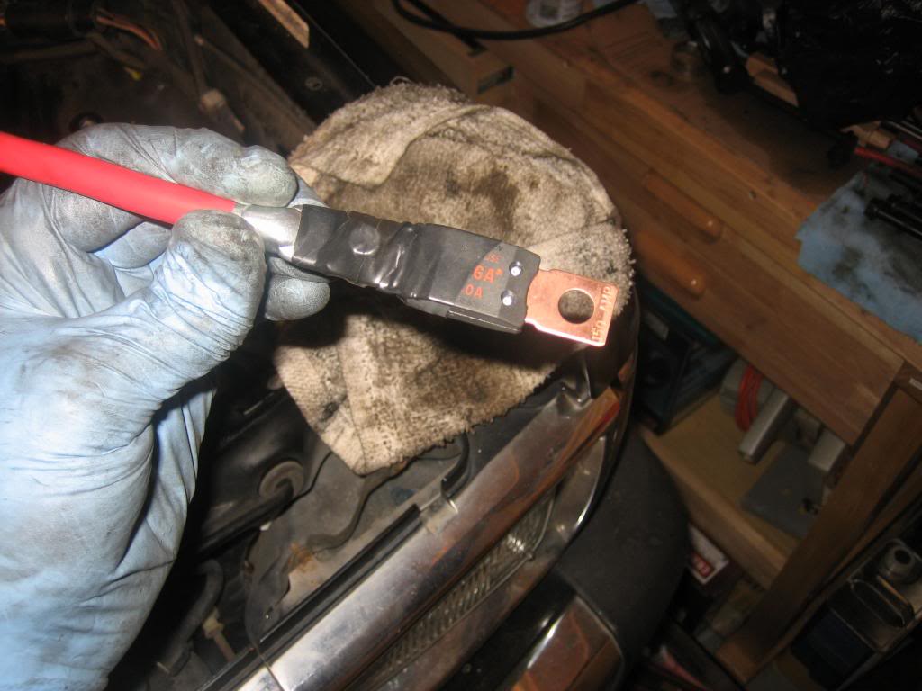
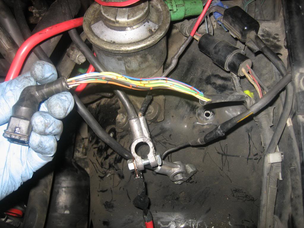
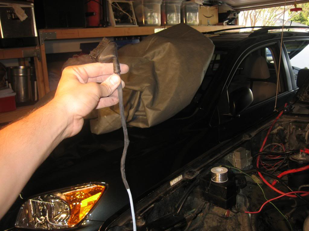
When I got home I also took some snaps of the wiring I had between my + battery and the fuse box.
Here is the whole thing where I cut it out (that brown part is the fusible link I THINK....):
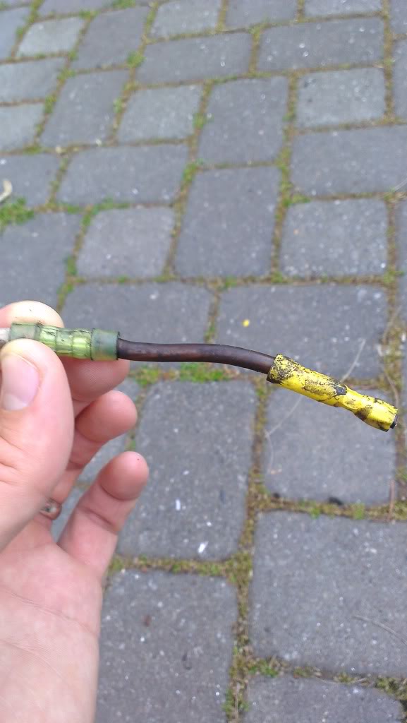
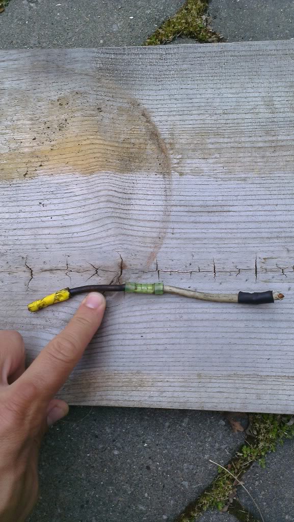
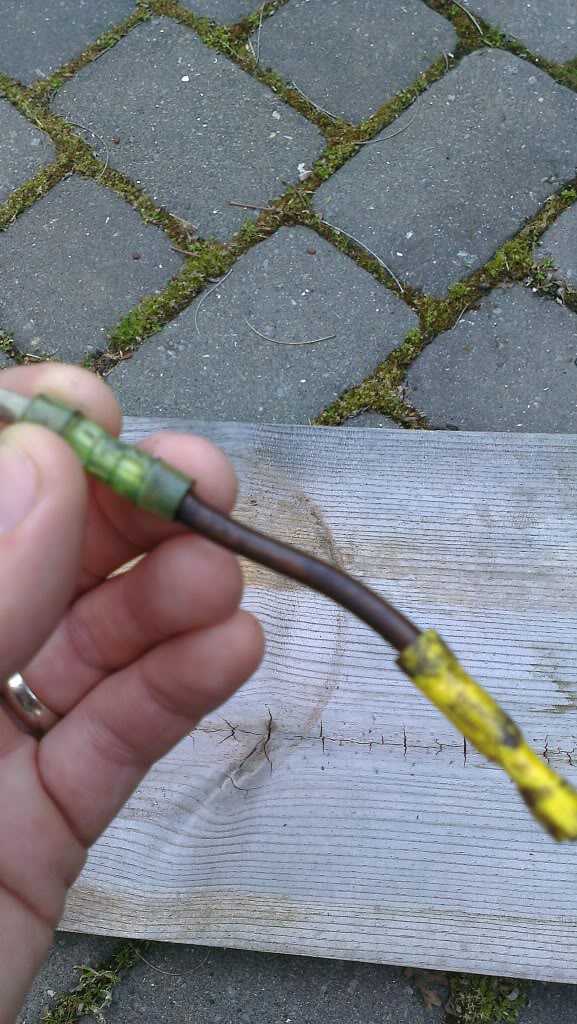
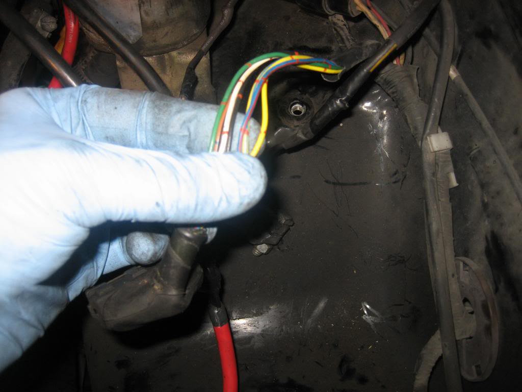
this is the wire from the fuse box:
When I got home I also took some snaps of the wiring I had between my + battery and the fuse box.
Here is the whole thing where I cut it out (that brown part is the fusible link I THINK....):
this is the wire from the fuse box:
04-08-2013, 08:07 PM
#179
Registered User
Thread Starter
iTrader: (2)
Join Date: Dec 2009
Location: Pleasanton, CA - SF Bay Area
Posts: 2,159
Likes: 0
Received 7 Likes
on
5 Posts
So, do I just need to get a section of fusible link wire that is thinner gauge than my 10 gauge new red wire, solder it in and insulate it? Is it that simple, for this wire?
04-08-2013, 08:21 PM
#180
Registered User
Join Date: Sep 2007
Location: San Francisco East Bay
Posts: 8,299
Likes: 0
Received 841 Likes
on
661 Posts
According to this manufacturer http://whiteproducts.com/fusible-faqs.shtml , fusible links are just pieces of wire like the parts store suggested. They suggest protecting wire with a fusible link "4" sizes smaller; so you'd use 14ga to protect your new 10ga wire.
This is all news to me. I had always thought there was something more to a fusible link, but maybe not.
This is all news to me. I had always thought there was something more to a fusible link, but maybe not.


