
Philbert's 87 4Runner Head Gasket & head replacement - take II
 04-09-2013, 02:55 AM
#181

Old school ones are a bit of solid core wire soldered in to place. I know this cause I've twisted them back together as a road side fix, don't think less of me I swear I put proper OEM ones in after we made it home. (subtext: yeah me too, I still don't think any random bit of multistrand will do the same job)
 04-09-2013, 03:41 PM
#182
Registered User
Thread Starter
iTrader: (2)
Join Date: Dec 2009
Location: Pleasanton, CA - SF Bay Area
Posts: 2,159
Likes: 0
Received 7 Likes
on
5 Posts
Thanks Co 94 PU, Scope and RAD4Runner for all the tips and insight. I looked at both your links, scope and Co 94, and it looks like i'll bet getting some 14 gauge fusible link, crimping, soldering, and heat shrinking that 10 gauge new wire I installed. Also plan to use wire loom on this wire in the engine bay, and probably run it around the back of the motor to avoid contact with the radiator, fan blades, etc.
Any input on the head bolts - whether to keep at OEM 58 ft/lbs, or tighten an extra 5 ft/lbs to 63 each?
Phil
Any input on the head bolts - whether to keep at OEM 58 ft/lbs, or tighten an extra 5 ft/lbs to 63 each?
Phil
04-09-2013, 04:34 PM
#183
...i'll bet getting some 14 gauge fusible link, crimping, soldering, and heat shrinking that 10 gauge new wire I installed. Also plan to use wire loom on this wire in the engine bay, and probably run it around the back of the motor to avoid contact with the radiator, fan blades, etc.
Phil
Phil
EDIT: Simplified to circuit similar to stock. Safer.
Best to use the "parallel connector", instead of a butt-connector. This way, standard wire and fusible wire will have direct contact, without possible weak metal of butt connector between them.

Also solder if possible to help prevent battery acid etc from getting into contact surfaces. then finally heat-shrink well for same reason. BTW, I got an 80-Watt soldering iron for thick auto wires from Frys. So far, it had worked really well for soldering two AWG 12 wires together.
I like the idea of running it behind the engine. Just like some ships power distribution is set up in a loop; If she takes a hit in the bow, the distribution line astern would still be intact and hopefully will keep her going.
Last edited by RAD4Runner; 07-25-2013 at 04:38 PM.
04-09-2013, 05:05 PM
#184
Registered User
Thread Starter
iTrader: (2)
Join Date: Dec 2009
Location: Pleasanton, CA - SF Bay Area
Posts: 2,159
Likes: 0
Received 7 Likes
on
5 Posts
Thanks Ray!
So, it sounds like your advice for 2 wires is:
1) For (new) 10 gauge wire running from battery + direct to fuse box, insert 14 gauge fusible link in-line, as close to battery as possible (it's in the diagram you have here, just above the battery).
2) This would mean re-connecting my stock alternator wire from the wiring harness, to the power post on the back of the alternator, right?
3) For (new) 4 gauge wire running from alternator to battery +, it appears you're instead recommending that I run that wire from alternator, to fusible link, to distribution post, then to the same fuse block junction where I hooked up my new 10 gauge wire?
I guess I still don't follow - that would mean that my 10 gauge wire would be serving the purpose of re-charging the battery, from the fuse box, rather than the direct connected, 4 gauge wire from alt to + battery? So, what's then the point of the 4 gauge wire in the circuit?
After reading all this, here is what I'm thinking:
1) Disconnect OEM ring connector from stock harness at alternator and tape up/tuck away (this wire runs to the fuse box and connects to the same mounts that the battery charge wire (the one with "all the butt splices") connects to. (DONE)
2) remove the "all the butt splices" charge wire from its mount in the fuse box and replace it with 10 gauge wire, which will then connect to + on the battery (DONE)
3) Install a 14 gauge fusible link in line with the new 10 gauge wire, close to the battery, using parallel connector, solder, and heat shrink to insulate (NOT DONE YET)
4) Run 4 gauge wire from the alternator to a function, with a 150A fuse between the alternator wire and junction, closest to junction. Run another short 4 gauge wire from other end of junction to + on battery.
Keep in mind I'm swapping the battery to the drivers side during all this.
Does that jive with what you guys are thinking? Do my concerns outlined above make sense? I removed the OEM charge wiring from the back of the alternator because I thought the wiring may not be sufficient with the increased output of the alternator (and that's also why I added the 4 gauge charge wire to the equation).
Phil
Last edited by Philbert; 04-09-2013 at 05:08 PM. Reason: typo
04-09-2013, 05:21 PM
#185
Autozone/Alldata says this.
Originally Posted by http://www.autozone.com/autozone/repairinfo/repairguide/repairGuideContent.jsp?pageId=0900c1528004d3c6
Tighten the cylinder head bolts evenly, in three stages and in the order shown, under Torque Sequences, to a specified torque of 52-63 ft. lbs
Could always go with the standard torque specs.
http://www.toyotapart.com/STANDARD_B...T-PG006-95.pdf
http://personal.utulsa.edu/~nathan-b.../8standard.pdf
Or any spec listed with the gasket, don't think you get those with an OEM one however.
Here is the TSB for the 3vz.

http://www.toyotapart.com/3VZ-E_CYLI...T-EG98-002.pdf
Last edited by Co_94_PU; 04-10-2013 at 12:50 PM. Reason: Fixed a quote, wrong part
04-09-2013, 06:58 PM
#186
Typed this out three times and my computers unhappy and keeps rebooting, really outta get around to replacing the capacitors...
You need the charge wire (B) and the feedback wire(S) close to the battery.
B: Alt->short heavy wire->FL->Battery
S: Alt->wire->FL->battery
To old FB: FL->Long heavy wire->FB
To new FB/JB: Short heavy wire->JB (optional: JB->FL->FB#3)
The problem is a multi route/path charge system will have differing voltages at the different points due to wire guage and proximity to the sense/feedback wire. The standard wiring drops about 1/2 volt between the ALT and the box where the B & S wires join the system, eg there is 15.5v at the ALT and ~15 at the box. If you multi drop the charge cable to the left side battery you get over charged since the sensor/feedback is on the other side of the engine bay. Granted this would be less than the 1/2volt with the wire upgraded.
And just because I have it, even if it's not relevent with my short version. Here is my version of RAD's diagram with the splice points and connection points from the 90-95 EWD book. Note the S wire connects to the 40A Fl and the charge to the 80A FL, this book also seems to ommit a "main FL" between the battery and relay block(fuse box).
04-09-2013, 07:00 PM
#187
 Seriously don't care if you take that advice but after typing 3-4 posts and loosing them I was gonna post something even if it was just a big long SCREEEAM. Actually came out rather clear in a short form
PS I was with you right up till #5 when you reminded us you were relocating the battery, then I saw the voltage difference problems. You can do 1-3, but #4 you need to ommit the atl->jb wire and let it run across the wire from the FB to the Bat. Just one guys opinion we'll see what the other guys thing.
Last edited by Co_94_PU; 04-09-2013 at 07:05 PM.
04-09-2013, 08:43 PM
#188
Guys,
Above is stock schematic. All circuit in black is stock (except I do not show other wires for clarity).
So Phil,
Yes, you reconnect your original alt "B" wire back where it came from, and your now new FL exactly in same place on fuse box the old one was, like this (the copper plate, right?) :

Basically, you will keep your stock circuit, but would simply be adding the new 4-gauge wire exactly in parallel with your stock alt "B" wire. Fuse or FL is inserted between new 4AWG wire and alt to protect it.
Above is simple enough. However, since you're relocating the battery, and probably leaving fuse box in stock location, now you would have to consider thicker batt to fuse box wire, right? Simpler and less messy than rewiring that fuse box.
Above is stock schematic. All circuit in black is stock (except I do not show other wires for clarity).
So Phil,
Yes, you reconnect your original alt "B" wire back where it came from, and your now new FL exactly in same place on fuse box the old one was, like this (the copper plate, right?) :
Basically, you will keep your stock circuit, but would simply be adding the new 4-gauge wire exactly in parallel with your stock alt "B" wire. Fuse or FL is inserted between new 4AWG wire and alt to protect it.
Above is simple enough. However, since you're relocating the battery, and probably leaving fuse box in stock location, now you would have to consider thicker batt to fuse box wire, right? Simpler and less messy than rewiring that fuse box.
04-09-2013, 08:59 PM
#189
this book also seems to omit a "main FL" between the battery and relay block(fuse box).
04-10-2013, 07:44 AM
#190
Registered User
Thread Starter
iTrader: (2)
Join Date: Dec 2009
Location: Pleasanton, CA - SF Bay Area
Posts: 2,159
Likes: 0
Received 7 Likes
on
5 Posts
Would of swore I'd seen that TSB but can't seem to find it.
Autozone/Alldata says this.
2nd hand quote from a "Clymer" manual, says 65.
Could always go with the standard torque specs.
http://www.toyotapart.com/STANDARD_B...T-PG006-95.pdf
http://personal.utulsa.edu/~nathan-b.../8standard.pdf
Or any spec listed with the gasket, don't think you get those with an OEM one however.
Here is the TSB for the 3vz.
http://www.toyotapart.com/3VZ-E_CYLI...T-EG98-002.pdf
Thanks - the FSM says 58, but I think there was a TSB put out later that stated a higher torque setting. And I've read guys on here crank them to 63, only if they have new head bolts usually....
That quote about cranking the distributor drive gear is wrong I think....FSM says 58 ft/lbs for that sucker.
04-10-2013, 08:18 AM
#191
Registered User
Thread Starter
iTrader: (2)
Join Date: Dec 2009
Location: Pleasanton, CA - SF Bay Area
Posts: 2,159
Likes: 0
Received 7 Likes
on
5 Posts
I noticed that too 
Again, THANK you guys for diving into this so much - it really helps me.
Sounds like I'll be:
1) Keeping my stock wiring (attach the charge wire from the alt harness to the back of the alt again)
2) Inserting a 14 gauge fusible link in the new 10 gauge wire from fuse box to battery (closer to battery side)
3) This is where I'm confused: For the 4 gauge wire from alt to battery (the "beefier charge wire"), I have a 150A in line fuse, closest to the battery. Sounds like you guys are saying to instead use a FL here (would be 8 gauge using the "rule of 4"). Am I fine with using the fuse instead of FL for this connection (since I have a FL on the smaller, 10 gauge charge wire)?
And, not sure that it matters, but in full discclosure, yes, RAD4Runner, that is the same brass plate I have in my fuse box that the FL wire was crimped to...but instead of crimping the new wire where the old was, I attached a ring connector (and soldered/heat shrunk), and then simply attached it to one of the existing posts that the other wire connections were already attached to (they thread through the two holes you see in the plate, in that image you posted. Since all wiring at this junction contacts that plate, I thought it wouldn't matter how it was attached and a ring connector seemed strongest. Any issues here?
Thanks again!
04-10-2013, 08:47 AM
#192
I noticed that too ...
I have a 150A in line fuse, closest to the battery. Sounds like you guys are saying to instead use a FL here (would be 8 gauge using the "rule of 4"). Am I fine with using the fuse instead of FL for this connection (since I have a FL on the smaller, 10 gauge charge wire)?
...I have a 150A in line fuse, closest to the battery. Sounds like you guys are saying to instead use a FL here (would be 8 gauge using the "rule of 4"). Am I fine with using the fuse instead of FL for this connection (since I have a FL on the smaller, 10 gauge charge wire)?
...brass plate...instead of crimping the new wire where the old was, I attached a ring connector (and soldered/heat shrunk)...
04-10-2013, 12:49 PM
#194
I ment to fix that, yeah it was the wrong section/line. Not much different but atleast it's the right part
Originally Posted by http://www.autozone.com/autozone/repairinfo/repairguide/repairGuideContent.jsp?pageId=0900c1528004d3c6
Tighten the cylinder head bolts evenly, in three stages and in the order shown, under Torque Sequences, to a specified torque of 52-63 ft. lbs
04-10-2013, 01:04 PM
#195
Registered User
Thread Starter
iTrader: (2)
Join Date: Dec 2009
Location: Pleasanton, CA - SF Bay Area
Posts: 2,159
Likes: 0
Received 7 Likes
on
5 Posts
Thanks - I may just do 63 ft/lbs.
For reference later (and for others) here is the tightening sequence for the head bolts:

You want to tighten them in 3 passes, not all at once (I think I did 20/40/58 ft/lbs in my 3 passes).
Ordered new distributor o ring and fuel pressure damper crush washers from dealer today (can't believe I lost those damn things in the process....maybe I'll find them before too long and can return the new parts....
For reference later (and for others) here is the tightening sequence for the head bolts:
You want to tighten them in 3 passes, not all at once (I think I did 20/40/58 ft/lbs in my 3 passes).
Ordered new distributor o ring and fuel pressure damper crush washers from dealer today (can't believe I lost those damn things in the process....maybe I'll find them before too long and can return the new parts....
04-11-2013, 09:38 AM
#196
Registered User
Thread Starter
iTrader: (2)
Join Date: Dec 2009
Location: Pleasanton, CA - SF Bay Area
Posts: 2,159
Likes: 0
Received 7 Likes
on
5 Posts
Sore lesson learned today
So, I ordered new crush washers, distributor o ring, and the bolt for the banjo fitting on the cold start injector from my local dealer yesterday.
They charged me over $30 for those parts (!).
I went on Toyotamotorparts.com to double check and it would have cost less than $10 (plus shipping of course but....).
I called the dealer and asked them if they price match and they said they price match LOCAL dealer pricing on parts but not internet pricing. Also, since these are all special order parts, there are NO RETURNS.
Pretty PO'd at myself for not doing due diligence first, and at them for this...we just spent almost $30K on our new RAV4 there last May
just wanted to rant
Oh, and if you miss the diagrams that used to be at www.toyotapartszone, www.toyotapartseast.com and www.toyotamotorparts.com have them, and pricing in the same ballpark.
04-11-2013, 04:15 PM
#197
Rad4Runner's Sore Lesson =D
[Don't worry, Phil, this would actually further simplify your setup. ]
Conclusion:
Revised circuit will prevent that and will be simpler
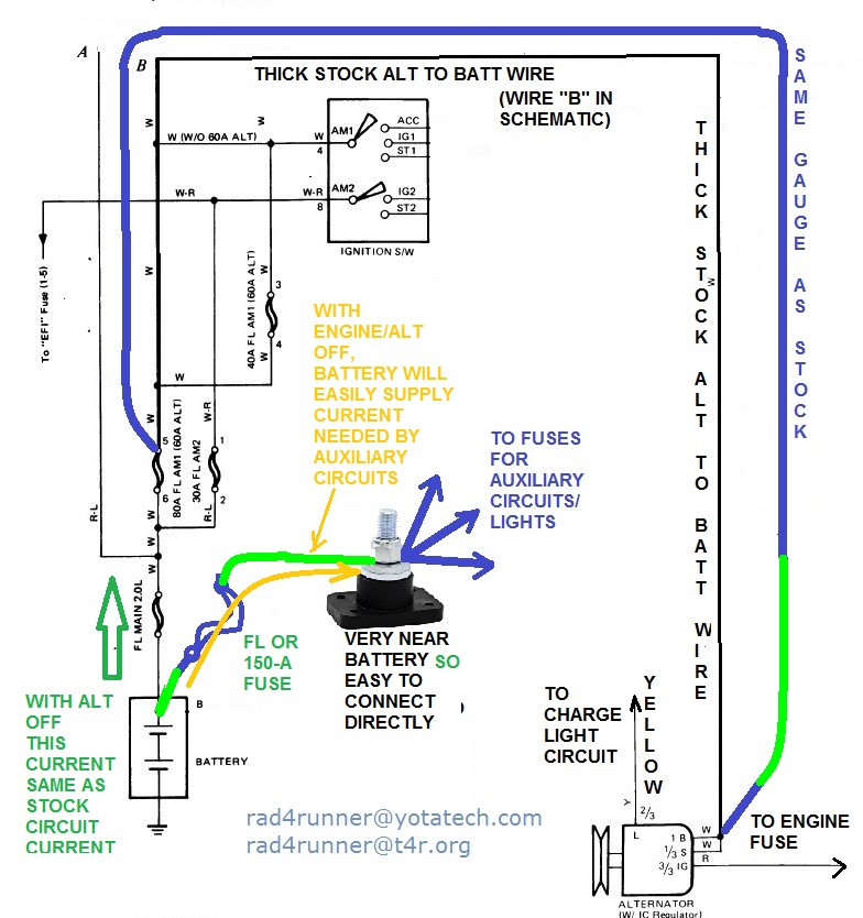
This time:
IF engine (hence, alt) were off battery can easily supply demand by auxiliary circuit. Not ideal but safe.
IF battery were low and still supplying power to aux circuit, charging current through main FL will still be controlled to proper/safe level by alt's regulator.
Your thoughts?
P.S. I just realized to day that If photo were uploaded to photobucket (like on this post), it will be displayed in bigger size than if it were uploaded to Yotatech album (on earlier posts^^), so for schematics where bigger display is needed, Photo bucket is better.
]Conclusion:
Revised circuit will prevent that and will be simpler

This time:
IF engine (hence, alt) were off battery can easily supply demand by auxiliary circuit. Not ideal but safe.
IF battery were low and still supplying power to aux circuit, charging current through main FL will still be controlled to proper/safe level by alt's regulator.
Your thoughts?
P.S. I just realized to day that If photo were uploaded to photobucket (like on this post), it will be displayed in bigger size than if it were uploaded to Yotatech album (on earlier posts^^), so for schematics where bigger display is needed, Photo bucket is better.
Last edited by RAD4Runner; 07-25-2013 at 04:36 PM.
04-11-2013, 11:27 PM
#198
OK guys, especially Philbert. I tried to merge Phil's two threads together and the original threads page 7 error fubarred the merged thread and it won't let me unmerge the two threads.
Phil- truly sorry for this. This issue is being forwarded to the site owners so we can get it figured out..
Thanks for your patience...
Phil- truly sorry for this. This issue is being forwarded to the site owners so we can get it figured out..
Thanks for your patience...
04-12-2013, 07:43 AM
#199
Registered User
Thread Starter
iTrader: (2)
Join Date: Dec 2009
Location: Pleasanton, CA - SF Bay Area
Posts: 2,159
Likes: 0
Received 7 Likes
on
5 Posts
Thanks Robb - at least we're able to see the last page of the thread (my first thread lived to page 6, and trying to get to page 7 or "last page" crashed it. Appreciate the attention!
Ray, again, you rock - thanks! And you're right about photobucket - much larger images So, sounds like I do what I said last post about this:
- Reconnect stock charge wire in alt. harness to back of alt charge post, and keep 4 gauge wire there too
- Insert FL (close to battery, not fuse box) in my 10 gauge new charge wire that runs from + on battery to FL plate in fuse box
- Run new 4 gauge wire from alt charge post to + on battery, with 150A fuse in line, closest to battery?
I went to NAPA yesterday and got 14 gauge FL (for my 10 gauge wire), and parallel connectors (the guy kept trying to tell me I needed a butt connector and I had to find the parallel connectors on shelf for him).
Ray, again, you rock - thanks! And you're right about photobucket - much larger images
So, sounds like I do what I said last post about this:- Reconnect stock charge wire in alt. harness to back of alt charge post, and keep 4 gauge wire there too
- Insert FL (close to battery, not fuse box) in my 10 gauge new charge wire that runs from + on battery to FL plate in fuse box
- Run new 4 gauge wire from alt charge post to + on battery, with 150A fuse in line, closest to battery?
I went to NAPA yesterday and got 14 gauge FL (for my 10 gauge wire), and parallel connectors (the guy kept trying to tell me I needed a butt connector and I had to find the parallel connectors on shelf for him).
04-12-2013, 10:24 AM
#200
That sucks. You're always a very helpful dude... So I think they'll stay ob trying to help fix it for ya, Phil. I wish I knew code lije those guys at times..... but I think my head is out of roo....... lol. I've had issues more with this site than an y other, from pc or now smart phone especially. Crashes when loading the site every 3-4 times. Literally locks up my phone with white screen for a.few seconds then just goes back to the home screen on my Note2. Lots of pages having gremlins... Wonder if its other site techs hating on yotatech?
Great to see u on the job here bubba.....been busy too, like crazy.. I Wish I could stop time like that movie and gather all I need and then give myself a week or month or so? Lol. ... "Clockstoppers" or something? Haha.
U doing SAS on her, Phil? Curious.
Great to see u on the job here bubba.....been busy too, like crazy.. I Wish I could stop time like that movie and gather all I need and then give myself a week or month or so? Lol. ... "Clockstoppers" or something? Haha.
U doing SAS on her, Phil? Curious.


