When you click on links to various merchants on this site and make a purchase, this can result in this site earning a commission. Affiliate programs and affiliations include, but are not limited to, the eBay Partner Network.
I am in the process of getting my new engine hooked up in my 91 Toyota pickup "22RE". I have a 140 amp alt that I bought from LC.
I would like to do the big 3 upgrade and I am wondering what to do with the stock wire that goes from alternator to 80 amp fuse in fuse box?
I have seen several posts saying to upgrade that wire and leave it in place and run a second 1/0AWG wire from alt to battery.
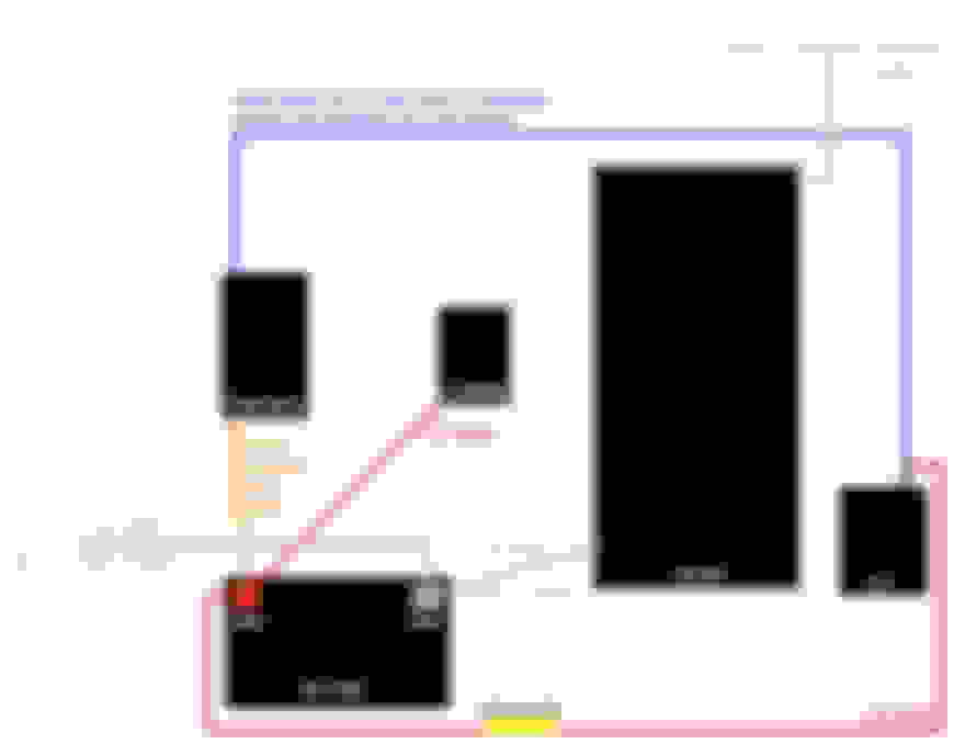
I have also seen some posts about deleting the stock wire but I don't think that is right. Please look at the diagram that I made showing my plan for wiring.
Anyone have any suggestions? Thanks.
The wire from the 80a fuse provide the field current, which isn't that substantial. If you really have a one-wire alternator, that wire no longer does anything.
The lc alternator that you posted is the one that I bought. It did come with an 8 gauge wire to use but I see a lot of people running directly from alt to battery with a big wire too. I do plan to hook up some lighting and stuff though so I thought running from alt to battery with a 1/0 gauge might be a good idea. I know 1/0 is overkill but I already have some 1/0 OFC laying around to use. Should I run both wires? Running the 8 gauge from alt to fusebox and 1/0 from alt to battery?
If you have the direct fit alternator, you have three wires (in addition to the fat "B" wire) to the connector. You need all of them; you don't have them on your drawing. The 8 gauge wire provided by LC Engineering replaces your current "B" wire to the 80amp fuse (because 140 amps is more than 60amps). It looks like you're "adding" a 1/0 wire through a 200amp fuse. That's fine (overkill, but if you have the wire, why not). Then you don't need the existing (usually yellow) fat stock wire. Having two wires only adds complexity if you have an 8ga (or larger) "B" wire. Remember that you need well crimped connectors on the ends of the wire; just sticking the wire under the nut and cranking down is completely useless.
The existing 3-wire connector (IG, L, and S) should be fine, without any wire replacements.
.. a lot of people running directly from alt to battery with a big wire too. I do plan to hook up some lighting and stuff though so I thought running from alt to battery with a 1/0 gauge might be a good idea. ...
Not a good idea. Those many people people are bypassing their critical fuses / FL with that alt direct to batt wire. See below.
Originally Posted by yotawilly
Yes there is also the connector with the 3 wires.
Those 3 wires do not carry load. They are not broken, Don't fix them.
Not a good idea. Those many people people are bypassing their critical fuses / FL with that alt direct to batt wire. See below.
Those 3 wires do not carry load. They are not broken, Don't fix them.
I don't plan to, I was going to keep those 3 as is and remove the stock B wire where it splits to the S wire, keeping the S wire in place and then use my 1/0AWG to wire directly from alt to 200A fuse to battery.
I seen some of your posts on here about it. Does that sound about right?
remove the stock B wire where it splits to the S wire, keeping the S wire in place and then use my 1/0AWG to wire directly from alt to 200A fuse to battery.
I seen some of your posts on here about it. Does that sound about right?
After looking around today I am a little confused now. My power wire for the alt where it connects to the alt post has 2 white wires coming out of it.
The power wire going to a little box behind the air box where it connects to a wire going to the 80 amp fuse in the fuse box and the other wire going to a connector next to it with the other alternator wires that come from the 3 wire connector that plugs into the alternator.
Then all these wires are wrapped and go along the front of the truck to the fuse box.
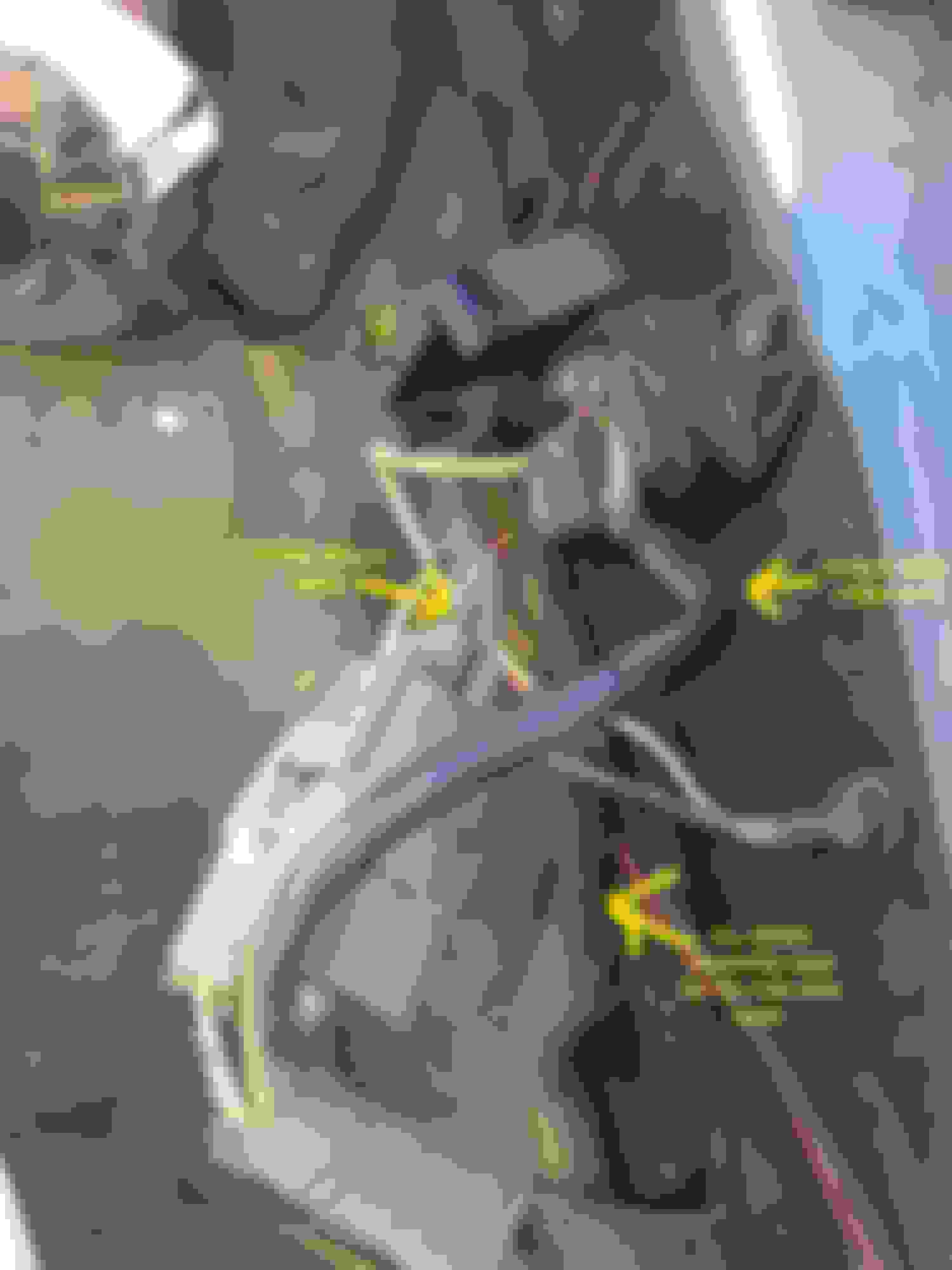
Here are some pictures.
Closer image
I am not exactly sure what that second white wire is but I am thinking that it probably still needs to be connected.
If that's the case, can I cut the power wire between the alt and that little box and leave the other white wire connected to the alt post and stack my new 1/0 wire to battery on top of it?
I am not exactly ready to do the wiring yet I am just trying to get a solid plan for when I am ready.
Best to thoroughly understand how things are set up (or messed up - LOL) before you dig into it. Hopefully someone with same truck can share schematic.
Normally, that stud block is just a disconnect. There should be 2 THICK wires of same thickness on it; one goes to alt stud terminal, the other to FL in fuse block. That is the "B" wire.
Last edited by RAD4Runner; 09-28-2020 at 10:59 AM.
Correct me if I'm wrong, as I usually am, but it seems to me that IF that big black wire that is labeled "Power Wire from Alt" is actually the power wire from the alternator, why is it going to a connection with ground?? The smaller, white wire, connected to the same screw terminal as that "Power Wire", can be seen going directly to the body ground nearby. Normally, a heavy gauge power wire isn't shorted direct to ground. Kinda defeats the entire purpose of the wire.
Or is my eye playing a trick on me, and the white wire on the same terminal as the power wire going into the wire bundle, and another white wire is coming out of the wire bundle, and connected to the ground lug? If that's the case, I feel like an idjit...
Yeah I am going to have to trace the wires and get a better look at things. I am going to put my old alternator on for now and deal with upgrading it later after I get my truck running and broke in a bit.
Yeah, the plastic block is a great insulator, no question. My question is whether the thin white wire on the plastic block going to the ground lug lower right of the picture, as it appears to, or am I seeing one white wire going to the ground lug from out of the wire loom, and the white wire going to the plastic block is a wire from out of the wire loom is a totally different wire?
It appears to me as though the white wire on the plastic block is going to the ground lug. Appears, I say. I might well be looking at totally different wires on the plastic block and the ground lug. It just looks, again, just looks to me, like the Power Wire going to the plastic block is shorted to ground through the white wire.
OR: Is the lug I mean, with a white wire and a white-black w/red marks wire on it, screwed into a plastic panel, or otherwise isolated from ground?
I'm probably just not seeing it right, is all. I thought I was looking at it from my good eye, but ya never know...
Pat☺
I will try to clear things up a bit.
I have a power wire that has 2 white wires.
I have a 3 wire connector that connects to the alt. It has a white, yellow and red wire.
I also have a black ground wire that connects to the power steering bracket.
My "b" power wire is going to the black plastic box then to 80 amp fuse and the second white wire I think goes to a 40 amp fuse "AM1".
The second white wire from the "b" power wire goes into a connector as seen in my pic below with the yellow and red wires from the 3 wire connector as well as the ground wire from power steering bracket.
The white wire from the 3 wire connector for alt goes into a different connector by itself.
All those wire and then wrapped up and go to fuse box.
I can easily upgrade the B power wire I am just unsure what to do about the other white wire that I am pretty sure goes to 40 amp fuse.
... My "b" power wire is going to the black plastic box then to 80 amp fuse and the second white wire I think goes to a 40 amp fuse "AM1".
The second white wire from the "b" power wire goes into a connector as seen in my pic below with the yellow and red wires from the 3 wire connector...
There should only be ONE "S" wire. It should splice to the B wire NEAR the battery and end up on the 3-wire connector. It should be as close a possible to the battery because it is the Sense wire. It tells regulator status of battery.
I can easily upgrade the B power wire I am just unsure what to do about the other white wire that I am pretty sure goes to 40 amp fuse.
That's all you really have to upgrade. Like I mentioned above, the rest do not carry load.
hey guys so I'm right in the middle of doing this upgrade got the 140 amp alternator from LCE , after reading through all this I'm still confused on the two white wires that go to alternator post , am I simply just cutting the power one out and then just reattaching it to post without B wire ? It would seem you would have to cause the other white wire is the S wire yeah ? And that one needs to stay on alternator post so that it gets a signal to the fuse box?, so basically in the end I would have the S wire hooked to alternator post and then my new thicker gauge wire also hooked to alternator post so B wire would run to battery , and S wire runs to the 80 FL ? So I basically just cut the B wire out at alternator and cut it by the fuse box , does all that sound right or am I missing something ?
Well if you call LC I'm pretty sure they'll tell you to run the new primary wire they supplied with the alternator directly to the battery without a fuse in addition to the existing stock wire(s). I put a fuse in anyhow when I installed mine. But when running their alternator, which has a smaller than stock pulley, I would consistently throw the belt around 5k rpm. I concluded it was a piece of junk / gimmick and put the stock unit back in. LC makes some nice stuff, and some garbage, hard to tell what is what since they only post positive reviews on their site. Let us know how it goes when you get it running, my advice would be to not modify the stock wiring at all, just run a new wire from bat to alt with a maxi fuse, and make sure you test rev it as high as you plan to when driving.

 09-26-2020, 01:30 PM