When you click on links to various merchants on this site and make a purchase, this can result in this site earning a commission. Affiliate programs and affiliations include, but are not limited to, the eBay Partner Network.
I'm upgrading my headlight wiring harness before installing some Hella E-Code housings with 80W/100W H4 bulbs. I'm excited to see the trail ahead at night!
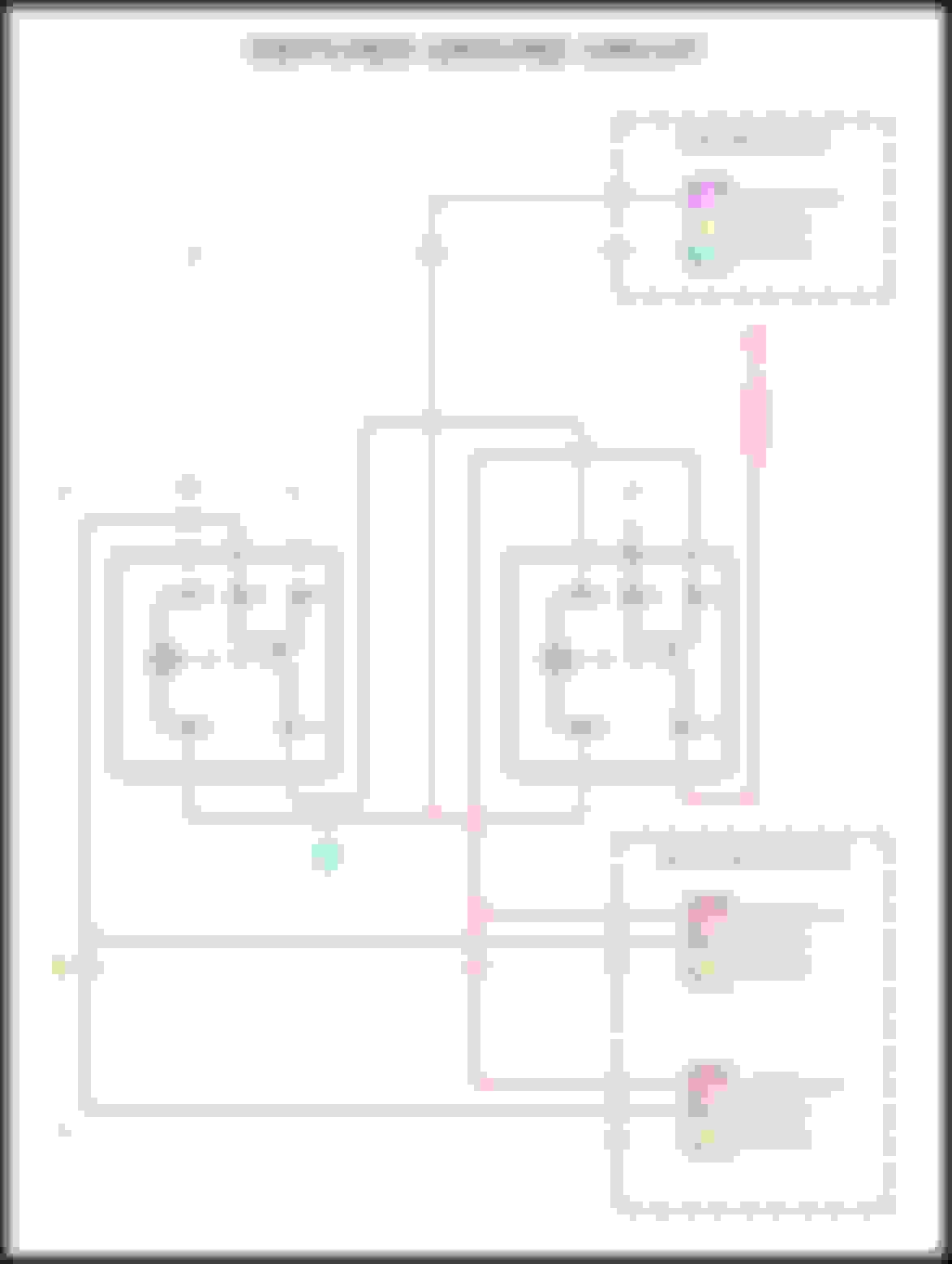
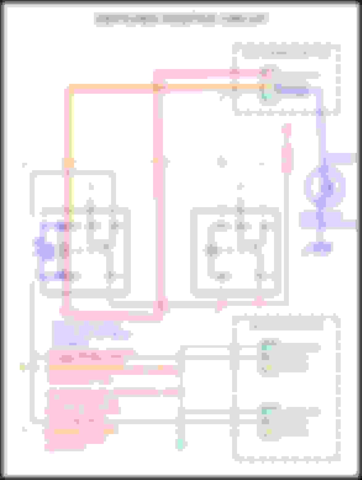
I have put together the two circuits below. From everything I've read/researched the Toyota Pickup (mine is a 1991 22R-E 5MT) has a switched ground system. I found this out after I had tried to use a ready-made harness but at this point; I can just put together my own instead of hacking a spendy ready-made solution.
Both of them utilize a single existing plug (driver's side, passenger doesn't matter - probably easier to use passenger side). With knowing that the current system is switched ground, both of these circuits I believe would accomplish the same goal. 4Crawler has a schematic on his website which adds circuitry to have the "high beam indicator" be lit. Honestly, I don't really care as I would know the high beam is on or not anyway so this is not a concern of mine. This is utilizing standard "Bosch-style" 5-pin or 4-pin automotive relays.
Is there a consideration with either of these setups that I should take in to account? Obviously I can use a 4-pin relay in place of the 5-pin(s) where it is not needed but it was just easier for generating the drawings.
Good idea upgrading the harness, especially before using high-wattage bulbs.
However,
Originally Posted by mdzu
... I found this out after I had tried to use a ready-made harness...
Bulbs with filaments would work either on switched-ground or switched-positive. Truck-lites like I have would work the same. No need to modify the harness you bought.
Switched ground in your diagram looks complicated and relays are interdependent. Why not simply have the OEM Driver low beam pin ground negative of the low-beam relay coil, and have the OEM Driver High-beam pin ground the high-beam relay coil?
Also, I have always applied positive to pin 86 of Bosch r3lay because most wiring schematics show it that way. Maybe it's not polarity sensitive?
If I absolutely need to use a conversion harness, I would convert to switched positive, so the always live 12V wiring would have a shorter run - just from fuse to relay. Safer that way.
In my case (here), I simply inserted ONE relay into the ground side of the circuit. Positive side still passes through the stock headlight relay. not a problem because I use lower wattage Truck-Lites. did not bother making the HB indicator work, either.
Last edited by RAD4Runner; 12-27-2020 at 06:49 PM.
Thank you for replying to my post - you've had lots of helpful information on this forum that I have read so much appreciated for all of your hard work and feedback to this community.
I agree that bulbs that are bi-directional (halogen, etc.) or LEDs designed to accept a switched ground circuit won't mind where the 12 VDC is coming from. I also agree the the Switched Positive (marked Switch Power in my diagram above) probably makes more sense to put in.
As far as pin 86 being the positive pin on a 5-pin Auto relay... I've seen both online - honestly it might not matter.
I picked up a A/C Fuse/Relay box from a late-90's Corolla at the junkyard yesterday which has slots for 2x 4-pin and 1x 5-pin Bosch relays with the included relays. Bonus - it already includes the 30 A fuse as well. Can easily mount it up in the engine bay and have all of this set up - just waiting for some of those little pigtails w/ ceramic h4 connectors to hack them up and connect bulbs/etc.
Your circuit is clever - I quite like it. Like you said, works great for the Trucklites and I remember reading a forum post, I believe by yourself, comparing the before/after with those LED lights. I like the halogen bulbs just because I can switch between the bulbs to find one that suits my needs (100/80 W bulbs are only $5 so if they burn out no big deal) but after all this fiddling it might have just been easier to grab those LED lamps. I can also change around to 100/55W, 60/55W, etc, or even LED bulbs within the housings, as I like.
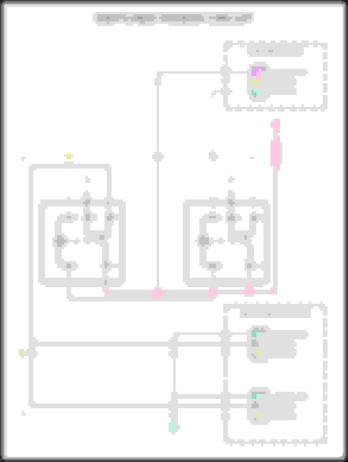
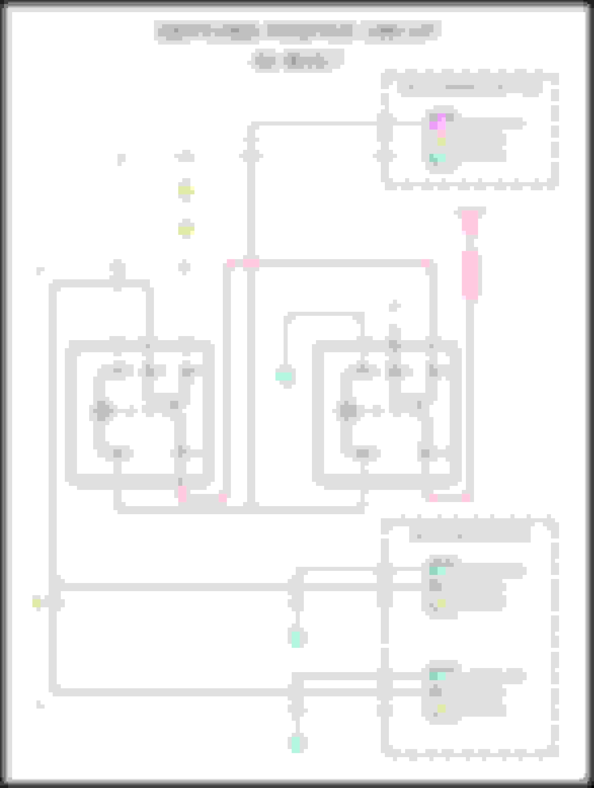
I've attached my "Switched Positive" setup which switches two separate 4-pin relays as you had mentioned. When switching between high/low beam it will de-energize one relay and energize the other. One thing I like about this one is that the load wire run is very short. Battery -> fuse -> relay -> bulb -> GND @ chassis next to the bulb. We'll find out if it matters switching between pin 86 vs. pin 85 for which is ground when I wire it up so I'll report back.
Just wanted to let you know that I hooked up my relays to a power supply and they will operate with pin 85/86 in either orientation. These are standard Bosch 4-pin automotive relays. Bosch 12 V 30 A Model # 0 332 014 167. I nabbed them from some various 90's Toyota(s) at the junkyard.
Nice and simple!
Thanks for answering the 85/86pin question. Good to know!
My thoughts in case you want to take care of high-beam indicator... Just to lazy to do mine - LOL! ...
In stock circuit when in high beam, "leakage" current through low-resistance low-beam filament causes voltage drop across the high-beam indicator and lights it. In low beam, the low-beam contact "sinks" that point (grounds the positive side of HB indicator), so indicator is off.
I believe the reason the HB indicator is disabled with the conversion is because the leakage current is now thru the higher resistance of the r3lay coil. I wonder if the lower current can still light an LED replacement. If not, a resistor (experiment with value) in parallel with the low-beam r3lay coil will increase that leakage" current to light an LED indicator bulb.
Cheers!
This is definitely a way to handle the issue on the high beam indicator - and your summary of how/why the high beam indicator works is succinct and easy to understand. What I will do is wire it up as shown and see where the high beam indicator is. As you said, indicator probably should not work. I have some voltage measurements and will take more to design a circuit that makes sense to get the indicator to work if I'm arsed to do it. Otherwise, I'd know when my high beams are on or not as I don't use high beams in the city anyway.
I ended up nabbing some new relays after twigging with the relay box from the Corolla. All of the wires in the thing are just way too small (22 AWG) and I tried to throw some 12 AWG female spade plugs in to it and they were giving me a lot of issues. Went w/ some Hella relays that have a seal for the wires on the bottom - seem nice and I'll see how everything works. Once this is all in and installed I'll be taking some pictures during the install and after and write a summary for everyone to use if they so choose.
What guage wire are you using for the power feeds?
I use 12AWG for each filament / bulb. Good for up to 20amps. A 100-watt bulb only draws 8+ amps. LED headlights even less.
I also prefer to use 12AWG for many other purposes because I do not want to keep too many different gage wires. Inventory is clutter, and managing clutter takes time away from adventures.
Last edited by RAD4Runner; 12-29-2020 at 08:50 PM.
What guage wire are you using for the power feeds?
Hello coopster,
I'm utilizing 12 AWG for the loaded lines and 18 AWG for all signal lines. Like RAD4Runner said, obviously can go bigger without any issue, however I already have 12 and 18 AWG spools handy.
Oh yeah, forgot about the control lines. Yes 18AWG for those. Not for current carrying capacity but for ease of working with and not as fragile as the stock 20 or 22 AWG.
Oh yeah, forgot about the control lines. Yes 18AWG for those. Not for current carrying capacity but for ease of working with and not as fragile as the stock 22 AWG.
Great. Thanks to both.
So to summarize, the headlight harness mod takes the 'current' for the original low/high beams as a signal to relay for the respective relays then?
I had looked at this all month or two ago, and on (was it Roger at 4crawler with the big write up?) and came to conclusion that as I had 9004 bulbs I probably did not need to worry or bother with an upgrade. Altho the wires to the sockets looks amazingly smallish. This is a 95 4runner body with front harness. And whatever amount of current does go thru the switch. Rad, hadn't you posted that? Or maybe it was dropzone.
Are you saying I should maybe rethink this? Good day to ask, 'cuz I'm feeling pretty coherent!!
I use 12AWG for each filament / bulb. Good for up to 20amps. ...
Actually, that's way more conservative than you need. (Toyota certainly didn't use wire that heavy.) The voltage drop difference between 12ga and 18ga (for 5 feet at 5amps, just to pick a case) is less than 1/3 volt. https://www.calculator.net/voltage-drop-calculator.html You might be picking the 20amp number from the National Electric Code (US) for 120vac house wiring (12ga wire is to be protected by a 20amp breaker, 14ga with a 15amp breaker). Long runs of house wiring concealed inside a flammable wall filled with scraps of paper is a different use case than an auto.
Of course, using larger wire doesn't hurt (as long as you terminate it in a connector that fits both the wire and the attachment).
My thoughts in case you want to take care of high-beam indicator... Just to lazy to do mine - LOL! ...
In stock circuit when in high beam, "leakage" current through low-resistance low-beam filament causes voltage drop across the high-beam indicator and lights it. In low beam, the low-beam contact "sinks" that point (grounds the positive side of HB indicator), so indicator is off.
I believe the reason the HB indicator is disabled with the conversion is because the leakage current is now thru the higher resistance of the r3lay coil. I wonder if the lower current can still light an LED replacement. If not, a resistor (experiment with value) in parallel with the low-beam r3lay coil will increase that leakage" current to light an LED indicator bulb.
Yes, original switch would now only carry lower current for the relay coils.
Originally Posted by coopster
......as I had 9004 bulbs I probably did not need to worry or bother with an upgrade.... ...And whatever amount of current does go thru the switch. ..
Roger said, "...after seeing the skimpy stock wiring and convoluted path that the headlight current takes, I decided it was time to upgrade the system wiring.". I and many others agree. That's why I upgraded mine altho I'm now using more efficient Truck-Lites.
Up to you to compare parts and labor for harness, vs cost and labor to replace bad dimmer-combo for bad contacts.
Great. Thanks to both.
So to summarize, the headlight harness mod takes the 'current' for the original low/high beams as a signal to relay for the respective relays then?
I had looked at this all month or two ago, and on (was it Roger at 4crawler with the big write up?) and came to conclusion that as I had 9004 bulbs I probably did not need to worry or bother with an upgrade. Altho the wires to the sockets looks amazingly smallish. This is a 95 4runner body with front harness. And whatever amount of current does go thru the switch. Rad, hadn't you posted that? Or maybe it was dropzone.
Are you saying I should maybe rethink this? Good day to ask, 'cuz I'm feeling pretty coherent!!
I believe that as long as you're running near the stock light wattage then it's probably not a huge concern. On the other hand, my understanding is that there is a decent voltage drop through the factory wiring, so you might see an improvement. RAD4Runner mentioned my concern - do this once, do it right, and never have to worry about burning up my combo switch on these 100 W bulbs that I'm going to be running which are far and above the stock level for high beams. Same with the low beams at 80 W.
Actually, that's way more conservative than you need. (Toyota certainly didn't use wire that heavy.) The voltage drop difference between 12ga and 18ga (for 5 feet at 5amps, just to pick a case) is less than 1/3 volt. https://www.calculator.net/voltage-drop-calculator.html You might be picking the 20amp number from the National Electric Code (US) for 120vac house wiring (12ga wire is to be protected by a 20amp breaker, 14ga with a 15amp breaker). Long runs of house wiring concealed inside a flammable wall filled with scraps of paper is a different use case than an auto.
Of course, using larger wire doesn't hurt (as long as you terminate it in a connector that fits both the wire and the attachment).
scope103,
14 AWG would be an appropriate application for this as well. It just happens that I have 12 AWG in a 500 ft. spool that I had gotten in a bin of parts, tools, etc. (including Freon!) so I'm using that - no reason to spend more on one size smaller. Same with the 18 AWG - I'm sure 20 / 22 would work fine for the signal lines; after all most of the wiring in the vehicle is probably 22 AWG anyway.
Thanks for the info on this - I've put some thought in to it and think I have an option that will work but this is good to know if it comes down to it. I want to see what the bulb looks like w/ just the coil resistance first but have an idea of what I'll need to do otherwise (including your option).
the high beam indicator was invisible for high beams in daylight after swapping the harness. it was very dimly visible at night with the high beams on. substituting the led bulb into the indicator restored its factory brightness, visible day or night.
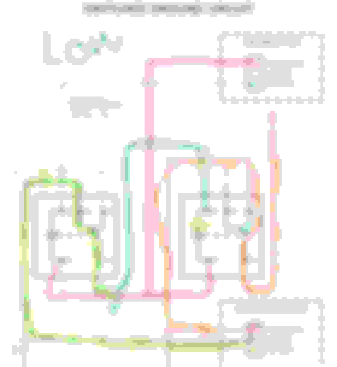
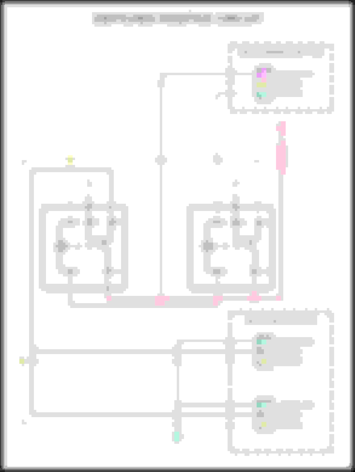
Just wanted to follow-up. I ended up installing a harness of the following design.
I utilized 12 AWG wiring for the red, gold, purple, and ground (from the bulb) lines and 18 AWG for the pink, cyan, and ground (from pin 86 on the relay) lines.
I went with a 20 A fuse. W = VI. (100 W/bulb * 2 bulbs) / 12.8 VDC = 15.625 A. I have not blown the fuse (and I didn't have a 30 A handy).
The reason I did this circuit design is that it ensures there's no current path back to ground for the low beams when the high beams are on. The high beam indicator does not work with this setup. I have shown a dashed line where-in someone could add a load resistor to provide current back to the high beam indicator. I have not added this functionality and don't care to as it's extremely obvious when the high beams are on.
. Obviously, there's lots of ways to skin this cat so you can go with any other variety of manufacturers, etc.
The light output of these bulbs is an immense improvement. In low beam I can see very well and the E-Code housings have a very sharp cut-off and it doesn't seem like I'm blinding anyone as I've aimed them. The 100/80W bulbs are pretty serious stuff in the high beam mode. They are approx. $6/bulb so easy to keep spares in a glovebox.

 12-26-2020, 11:25 PM