DIY headlight wiring harness upgrade for low $$
#143
Registered User
iTrader: (1)
I bought exactly the listed components from radio shack and already had wire/fuses, and connectors from autolumination.com; was a fun build and puts out TONS more light for sure. I was blown away with the difference. My only problem now is that I can't stop burning out OSRAM nightbreakers; on my 4th and final bulb in about a year's time. Gonna have to do something different if I keep munching thru bulbs.
#144
Registered User
Join Date: Apr 2008
Location: Glendale AZ
Posts: 292
Likes: 0
Received 0 Likes
on
0 Posts
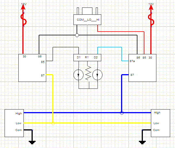
Can someone explain this schematic to me as far as the two diodes and resistor? I followed this schematic but did not use the resistor/diode block. My headlights work great, much brighter and whiter light output. I assume because I did not wire in the diodes and resistors my low beams stay on with my high beams. I guess that's fine but I don't understand how using the diodes and resistor will work. To me it looks like current from the original headlight plug flows out of the low beam connector and into the resistor (R1) but the cathode (-) of the diode (D1) would block current from entering the low beam relay because it would be reverse-bias, how could the low beams even turn on?
#145
Contributing Member
Join Date: Mar 2003
Location: COTKU,Ontario,Canada
Posts: 11,334
Likes: 0
Received 0 Likes
on
0 Posts
That schematic looks a little off to me too... one of the diodes may be reversed for one thing...
as to having both high and low beam engaged together this can lead to overheated bulbs and reduced bulb life for one thing... because of the high heat they could also be more susceptible to mechanical failure from vibration/jarring...
as to having both high and low beam engaged together this can lead to overheated bulbs and reduced bulb life for one thing... because of the high heat they could also be more susceptible to mechanical failure from vibration/jarring...
#146
Registered User
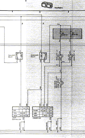
It's not what is in the drawing that makes that confusing, it's what's not in it that makes it confusing. The high beam indicator light is what throws everything of. The current that goes though the high beam indicator light is enough to trip a relay but not enough to light a light bulb. You'd really have to look at the oem wiring diagram to understand it.
#148
Registered User
Join Date: Aug 2010
Location: Oregon, USA
Posts: 2,027
Likes: 0
Received 0 Likes
on
0 Posts
#149
Registered User
Join Date: Apr 2008
Location: Glendale AZ
Posts: 292
Likes: 0
Received 0 Likes
on
0 Posts
Ok, if i have current flowing out of COM then back into LO i can see how that would work; but what about the high beam relay now? 4crawler says he uses a DPST relay for the high beam, this throws me off because it would appear that pin 87a on the high beam relay would always be energized. So when you turn on the headlights to low beam current will come from both relays into both diodes and then into R1 and then to the low beam pin in the factory connector. I can see that but when high beams are turned on the high beam relay turns pin 87 on to light the high beams, now you lose any current being fed through pin 87a to feed the high beam indicator in the dash, cause pin 87 is now energized. I wonder if 4crawler meant to say DPDT relay for the high beams? In my head I can see that working, but then again many things in my head don't work 

#150
Registered User
iTrader: (4)
stop
look at this:

(hard to see, but you can get the idea)
the h/b indicator is grounded when the l/b are on. current always flows through common, and when the h/b are on, it allows the trons to flow through the h/b indicator. the schematic will help you understand it better. (haynes manual)
he did not mean to say "dpdt" as there is no common "bosch" style relay like that
look at this:

(hard to see, but you can get the idea)
the h/b indicator is grounded when the l/b are on. current always flows through common, and when the h/b are on, it allows the trons to flow through the h/b indicator. the schematic will help you understand it better. (haynes manual)
he did not mean to say "dpdt" as there is no common "bosch" style relay like that
Last edited by irab88; 03-15-2012 at 10:12 AM.
#152
Registered User
Join Date: Apr 2008
Location: Glendale AZ
Posts: 292
Likes: 0
Received 0 Likes
on
0 Posts
I think I get it now and you're right, it's not a DPDT, I mislabeled it. I was thinking of the DPST type relay but thought it was called a DPDT. I looked it up to clarify...
http://www.vtiinstruments.com/Suppor....aspx?FaqID=97
Now that I know how that relay works it makes sense now, when pins 85 & 86 on the high beam relay are energized, pins 87 & 87a will see full battery voltage so the high beams will turn on and current will go back through D2 & R1 to light the high beam indicator on the dash.
#153
Registered User
iTrader: (4)
87a is disconnected when 87 is connected (then the coil is energized).
the issue most of us are having is trying to incorporate a switched positive system into a switched negative circuit.
relay basics:
http://www.bcae1.com/relays.htm
the issue most of us are having is trying to incorporate a switched positive system into a switched negative circuit.
relay basics:
http://www.bcae1.com/relays.htm
#154
Registered User
Join Date: Apr 2008
Location: Glendale AZ
Posts: 292
Likes: 0
Received 0 Likes
on
0 Posts
If 87a is disconnected when 87 is connected this would make the relay a SPDT??
This is what confused me for awhile cause I thought that's what that type of relay was. If it was a SPDT only one pin, 87 or 87a would be connected to allow current flow, not both at the same time. To me it looks like both need to have current flowing in order for the high beams to come on and to have the high beam indicator on the dash light up. Which means 87 & 87a are both on at the same time. Or am I still missing something here?
Taken from Rodger's/4crawlers page - "Note that high beam relay contacts 87 and 87a turn on and off at the same time (i.e. DPST or 2-Form-A design)."
To me on and off at the same time means DPST relay;
http://www.vtiinstruments.com/Suppor....aspx?FaqID=97
In the link you sent me The Bosch style relay in the schematic with 5 pins is a single pole double throw type relay, it looks like the same type of relay in 4crawlers schematic, 5 pins with 87 & 87a.
#156
Registered User
Join Date: Apr 2008
Location: Glendale AZ
Posts: 292
Likes: 0
Received 0 Likes
on
0 Posts
It looks like a DPST relay requires 6 pins, 2 for the coil and 2 for each loaded circuit, which totals 6 pins.
I wish I could do a mock up circuit like your doing right now, I printed his schematic out and just made some changes but I can't up load it right now being that I'm at work.
How about this? It looks possible to just use two SPST relays for the same result. Have one relay turn on the high beam indicator and the other relay turn on the high beams. Have pins 86 tied together on both relays and the same for pins 85 so both relays come on at the same time.
#157
Registered User
Join Date: Apr 2008
Location: Glendale AZ
Posts: 292
Likes: 0
Received 0 Likes
on
0 Posts
or just use one relay for the high beam and tap off pin 87; two wires come off that pin to turn on the high beams and to also direct current back to to D2 and R1?
#159
Registered User
Join Date: Apr 2008
Location: Glendale AZ
Posts: 292
Likes: 0
Received 0 Likes
on
0 Posts


