
DIY headlight wiring harness upgrade for low $$
 01-13-2010, 05:56 PM
#1
Contributing Member
Thread Starter
I've seen this discussed a few times, but have still never seen a set-by-step write up, or even pictures of a full install
until now
don't hate me because it's a Jeep in the page the wiring is all the same, and this is REALLY good info, that I will be personally using here shortly when I install my new H4 conversion lights that I just got in
http://www.go.jeep-xj.info/HowtoHeadlightLoom.htm

until now
don't hate me because it's a Jeep in the page
the wiring is all the same, and this is REALLY good info, that I will be personally using here shortly when I install my new H4 conversion lights that I just got in http://www.go.jeep-xj.info/HowtoHeadlightLoom.htm


 01-13-2010, 06:11 PM
#3
Registered User
Join Date: Oct 2006
Location: GrangeVille, Idaho
Posts: 4,166
Likes: 0
Received 10 Likes
on
10 Posts
Thats a good write up, i saved it for future use. I just got a 160 AMP alternator for my 4Runner, so along with that and this head light mod it should be a nice improvement.
01-14-2010, 06:06 AM
#4
Registered User

Daniel Stern:
http://www.danielsternlighting.com/t...ys/relays.html
By the way, make sure to use SEALED relays! And if you're using relay connectors like you should (not just crimp on female spade connectors)- use RTV to seal the back side of the connector. Then put dielectric grease in the connector for a 100% waterproof setup. I've never had a relay fail on me, even with one mounted in the back of the truck on the frame through northeast winters with lots of road salt.
Also, now would be a good time to upgrade your crappy stock headlight connector to a ceramic connector, and use 14awg wire. If you're tricky like me, you can add a simple diode in the wiring for dual beams. (dual beams = low beam stays on with highs, but high beams turn off with lows, a very easy modification.)
http://www.danielsternlighting.com/t...ys/relays.html
By the way, make sure to use SEALED relays! And if you're using relay connectors like you should (not just crimp on female spade connectors)- use RTV to seal the back side of the connector. Then put dielectric grease in the connector for a 100% waterproof setup. I've never had a relay fail on me, even with one mounted in the back of the truck on the frame through northeast winters with lots of road salt.
Also, now would be a good time to upgrade your crappy stock headlight connector to a ceramic connector, and use 14awg wire. If you're tricky like me, you can add a simple diode in the wiring for dual beams. (dual beams = low beam stays on with highs, but high beams turn off with lows, a very easy modification.
)
Last edited by shaeff; 01-14-2010 at 06:07 AM.
01-14-2010, 03:22 PM
#5
Contributing Member
Thread Starter
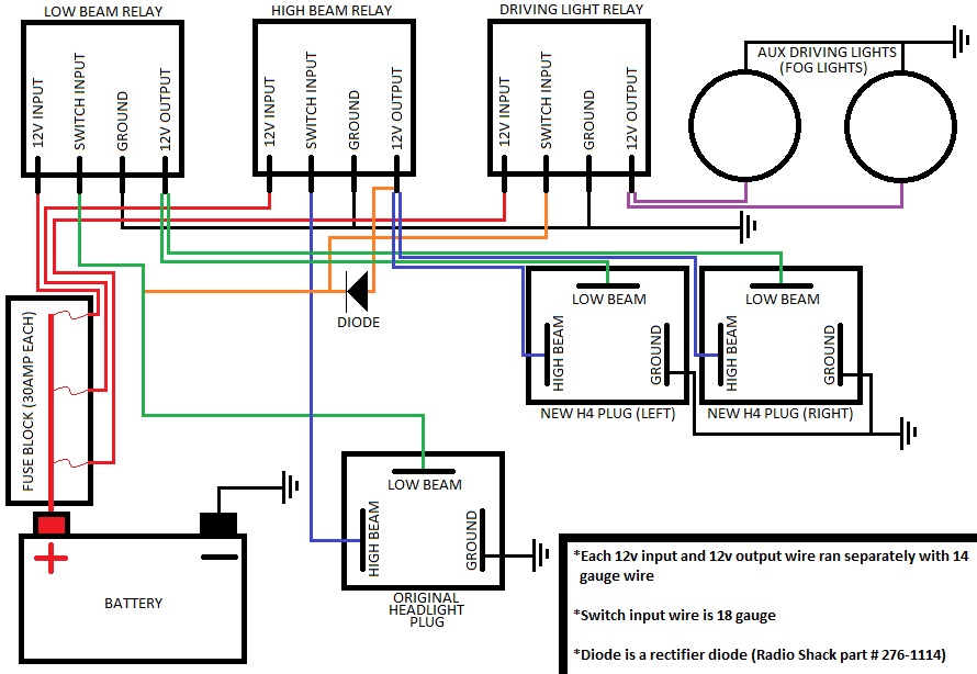
diode from the high beam output at the relay to the low beam signal input at the relay
because also with doing this, I'm also going to run the relay signal input of my driving lights to the output of the low beams, so the driving lights will be on with both the low and high beams
Last edited by iamsuperbleeder; 01-14-2010 at 03:24 PM.
01-15-2010, 09:57 PM
#7
Registered User
not that tricky, and I already have plans on doing so
diode from the high beam output at the relay to the low beam signal input at the relay
because also with doing this, I'm also going to run the relay signal input of my driving lights to the output of the low beams, so the driving lights will be on with both the low and high beams
diode from the high beam output at the relay to the low beam signal input at the relay
because also with doing this, I'm also going to run the relay signal input of my driving lights to the output of the low beams, so the driving lights will be on with both the low and high beams
 Glad to see (no pun intended) that someone else is doing it! The extra light is fantastic!
Edit: I just read over that link you posted, - get relay harnesses. Don't use spade connectors on the relays. Do as I said above, and you'll NEVER have a problem. With spade connectors, you get corrosion quite easily.
Last edited by shaeff; 01-15-2010 at 10:06 PM.
Trending Topics
01-15-2010, 10:33 PM
#8
Registered User
Join Date: Dec 2009
Location: Austin, TX
Posts: 268
Likes: 0
Received 0 Likes
on
0 Posts
Doesn't a diode mean a voltage drop? That means less voltage to the lamps, and need for a high-wattage resistor that can dissipate some heat. Try disconnecting your highs, and flip between high and low, see if the lows are a bit dimmer when the high beams are on.
There must be a way to rewire if you want the lows always on; just hook the lows up before the relay and leave the highs as they are. Or maybe I'm missing something....
There must be a way to rewire if you want the lows always on; just hook the lows up before the relay and leave the highs as they are. Or maybe I'm missing something....
01-16-2010, 06:05 AM
#9
Contributing Member
Thread Starter
Doesn't a diode mean a voltage drop? That means less voltage to the lamps, and need for a high-wattage resistor that can dissipate some heat. Try disconnecting your highs, and flip between high and low, see if the lows are a bit dimmer when the high beams are on.
There must be a way to rewire if you want the lows always on; just hook the lows up before the relay and leave the highs as they are. Or maybe I'm missing something....
There must be a way to rewire if you want the lows always on; just hook the lows up before the relay and leave the highs as they are. Or maybe I'm missing something....
a diode allows power to only flow in one direction
Think about it like this. Wiring in a resister would be like taking a 3" exhaust, cutting it in half, and welding in a section of 1" pipe... all it's going to do is restrict the flow. But, wiring in a diode would be like putting a flapper-tip on the end of the exhaust. It's like a one-way valve, and is only going to let the flow go in one direction
Last edited by iamsuperbleeder; 01-16-2010 at 12:26 PM.
01-16-2010, 08:09 AM
#10
Registered User
Doesn't a diode mean a voltage drop? That means less voltage to the lamps, and need for a high-wattage resistor that can dissipate some heat. Try disconnecting your highs, and flip between high and low, see if the lows are a bit dimmer when the high beams are on.
There must be a way to rewire if you want the lows always on; just hook the lows up before the relay and leave the highs as they are. Or maybe I'm missing something....
There must be a way to rewire if you want the lows always on; just hook the lows up before the relay and leave the highs as they are. Or maybe I'm missing something....
If you were to put that diode directly from the high beam to the low, you'd burn it (and likely some of your wiring) up in a flash. They can carry high voltage, but not a lot of amperage.
Cliffnotes: you can only use the diode to trip the relays, NOT the actual lights. Let the relays take the current!
01-16-2010, 08:50 AM
#11
Registered User
Join Date: Dec 2009
Location: Austin, TX
Posts: 268
Likes: 0
Received 0 Likes
on
0 Posts
Shaeff, that makes a lot more sense. I'd like to see a diagram.
Super Bleeder, thanks for the description. Your analogy works well for describing diode forward voltage drop. The flap takes a small amount of force for the exhaust to push and hold open. The voltage drop is typically about 0.7V, which is about 6% in our 12V systems. Read more here:
http://www.kpsec.freeuk.com/components/diode.htm
This doesn't matter if the diode isn't going inline with the light bulb, for a relay it's no problem.
I don't know how the circuits are wired, but here's what I was thinking:
01-16-2010, 01:38 PM
#12
Contributing Member
Thread Starter
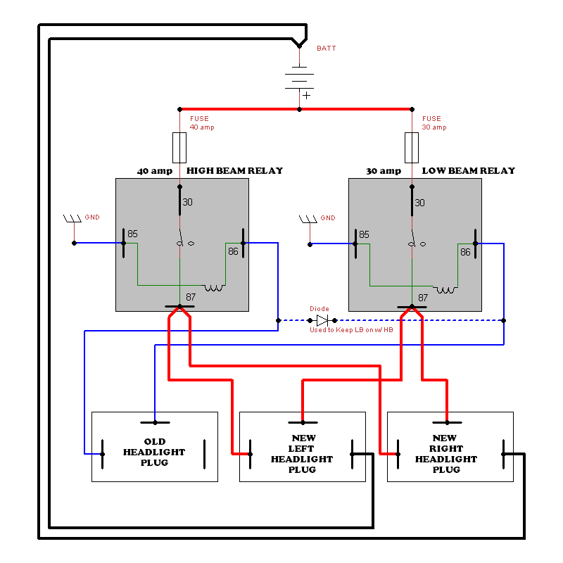
Schematics are fun to make 
I picked up all of the supplies today minus the relays that I already had (cost about $40 for the supplies, but I ended up doubling that cost by getting a new soldering gun, and some other little things, lol), and will probably get started on the harness tomorrow, since the truck's broke down anyway due to the alternator going out
Soldering and heat shrinking all the connections too
Last edited by iamsuperbleeder; 01-16-2010 at 01:49 PM.
01-16-2010, 02:15 PM
#13
Registered User
Dammit Superbleeder you beat me to it, anyway mines nicer. lol. I hope this is right, someone please correct me if I am reading the tutorial wrong and let me know what I need to fix in the schematic. Anyway here we go. Basically the tutorial is using the factory headlight sockets to power the new relays which in turn operate the new sockets. I have added a dotted line with a diode which I believe is the right way to keep the low beams on with the high beams. Hope this helps someone.
Last edited by xxxtreme22r; 01-16-2010 at 02:16 PM.
01-16-2010, 03:56 PM
#14
Contributing Member
Thread Starter
that's basically the same setup, only I'm adding on a set of driving/fog lights that kick on with the headlights too
and I'm also installing some Hella 500FF's on the tube bumper on an independantly operated cuircut
and I'm also installing some Hella 500FF's on the tube bumper on an independantly operated cuircut
01-16-2010, 07:56 PM
#15
Registered User
Years ago I was going to make my own but after I priced the sealed high quality relays and after I seen how expensive they were at the time I just bought the kit. I bought it from Northwest Offroad. It is actually the Painless Wiring kit here: http://www.painlesswiring.com/webcat...=4x4%20OffRoad
I did not pay that price. I think it was roughly $60 but I cannot remember. High quality wire and relays were used. I believe they are either Hella relays or Bosch.
James
I did not pay that price. I think it was roughly $60 but I cannot remember. High quality wire and relays were used. I believe they are either Hella relays or Bosch.
James
01-16-2010, 08:08 PM
#16
Contributing Member
Thread Starter
well I've already got a set of good 40amp relays that I got from work for free, so that was a discount for me there
plus, I've always enjoyed the puzzles of wiring
plus, I've always enjoyed the puzzles of wiring
Last edited by iamsuperbleeder; 01-17-2010 at 04:08 PM.
01-16-2010, 08:32 PM
#17
Contributing Member
Join Date: Mar 2003
Location: COTKU,Ontario,Canada
Posts: 11,334
Likes: 0
Received 0 Likes
on
0 Posts
Looks good guys but why use woosie 14AWG (only one size up from the 16AWG in stock sys.)? Step up to a more manly 12AWG or even 10AWG (if your chest is hairy enough ). Yes the wire will be heavier and may be a little stiffer but the resistance will be even lower and you'll be able to go to some seriously high lamp wattages with it.
). Yes the wire will be heavier and may be a little stiffer but the resistance will be even lower and you'll be able to go to some seriously high lamp wattages with it.
01-16-2010, 09:04 PM
#18
Registered User
Although you will see an improvement over the old wiring with 14awg, 12awg is a better choice. 10awg isn't enough of an improvement over 12 to warrant the extra cost and weight, IMO. Check out the Daniel Stern link I posted earlier in the thread.
And use heat shrink that oozes adhesive if you want it truly waterproof.
And use heat shrink that oozes adhesive if you want it truly waterproof.
01-16-2010, 11:16 PM
#19
Registered User
Join Date: Jul 2008
Location: Grew up in S.C.V, So Cal.....now in Hampstead, NC
Posts: 4,592
Likes: 0
Received 0 Likes
on
0 Posts
'Bleederdude, please do your own write up, with pic for each stage, and write it up, say for some1 who doesn't know or really understand wire....like me! I've wanted to something very similar, but using Hella 550's....
01-17-2010, 04:20 PM
#20
Contributing Member
Thread Starter
too late freak 
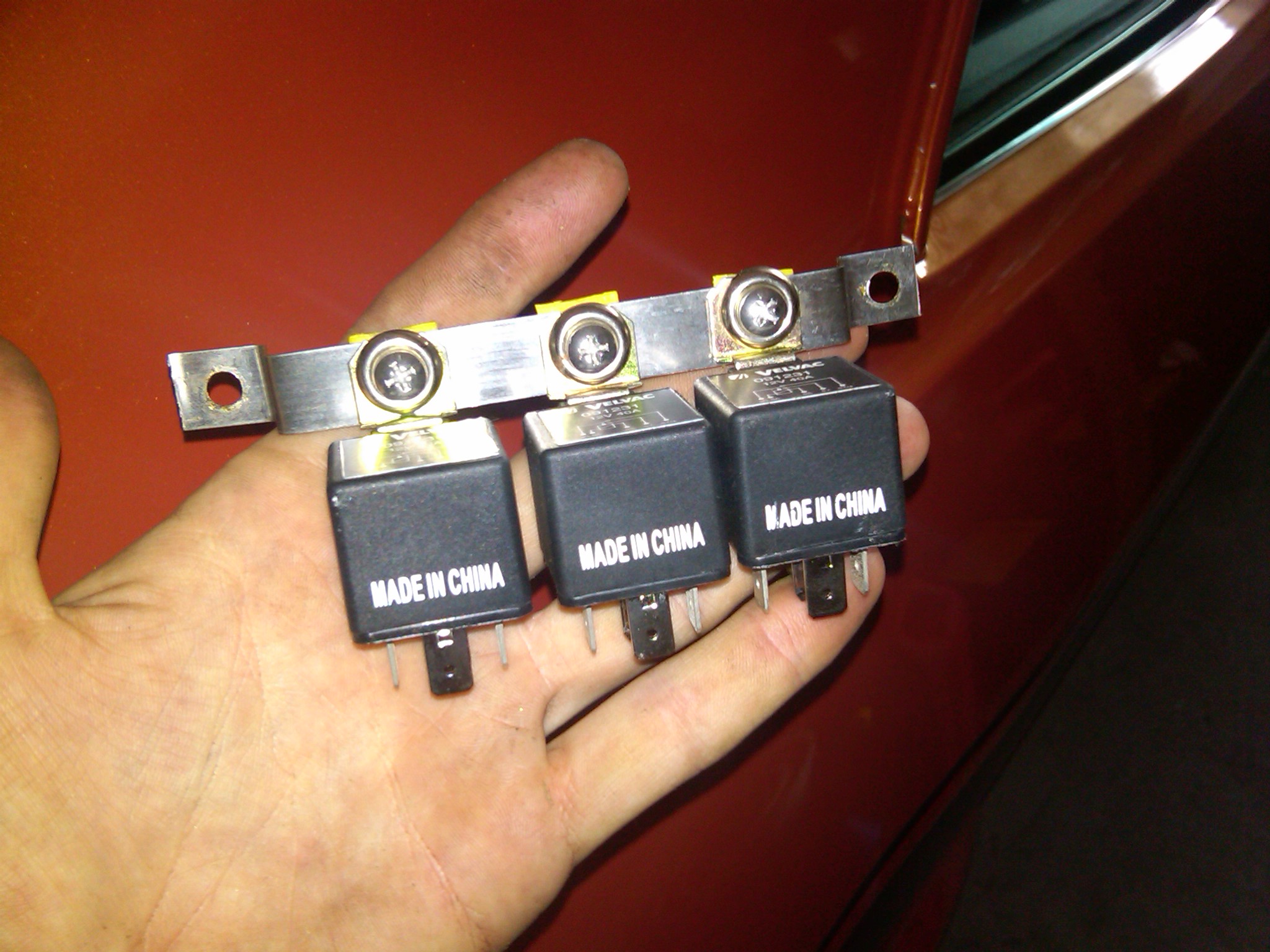
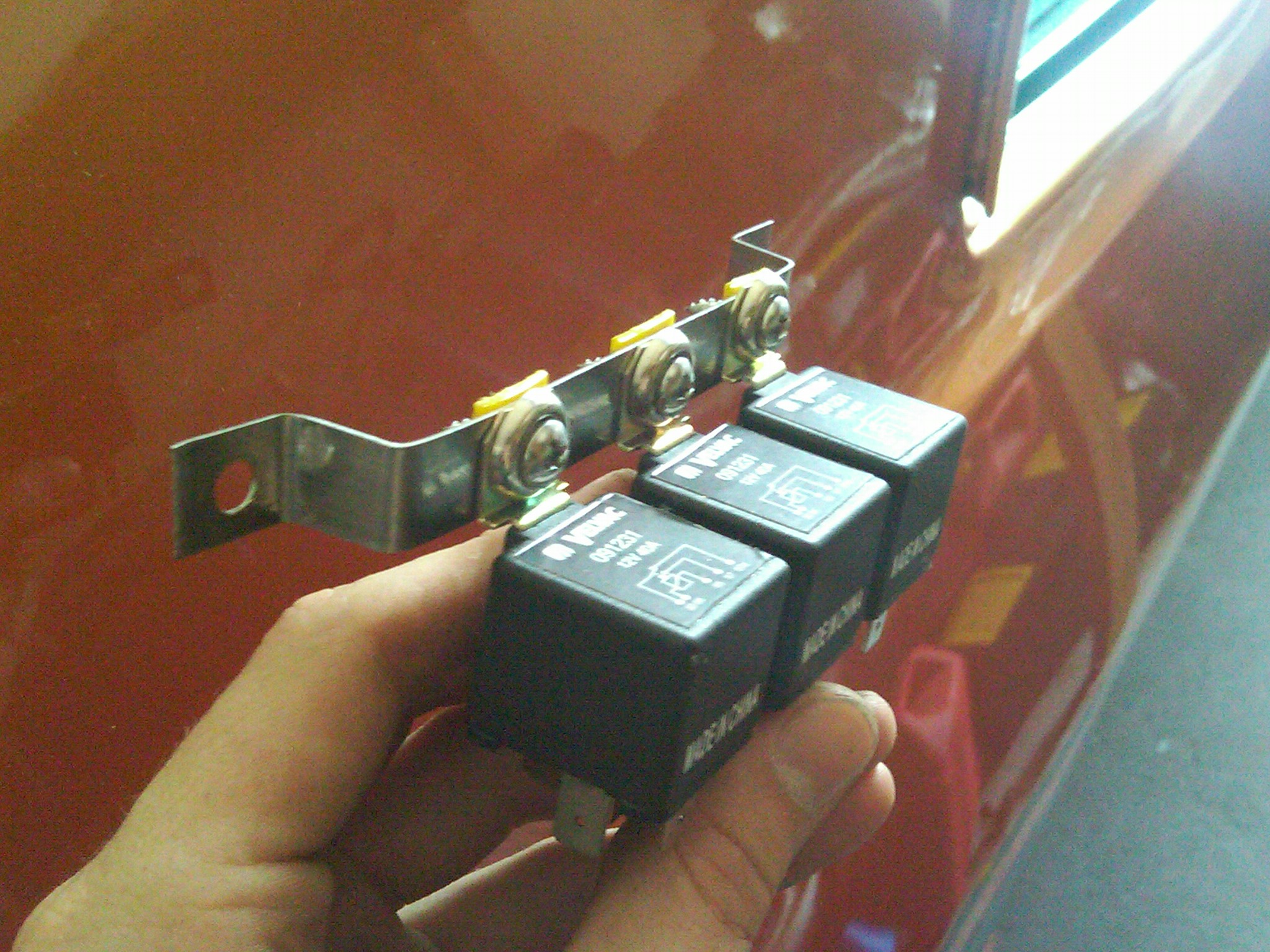
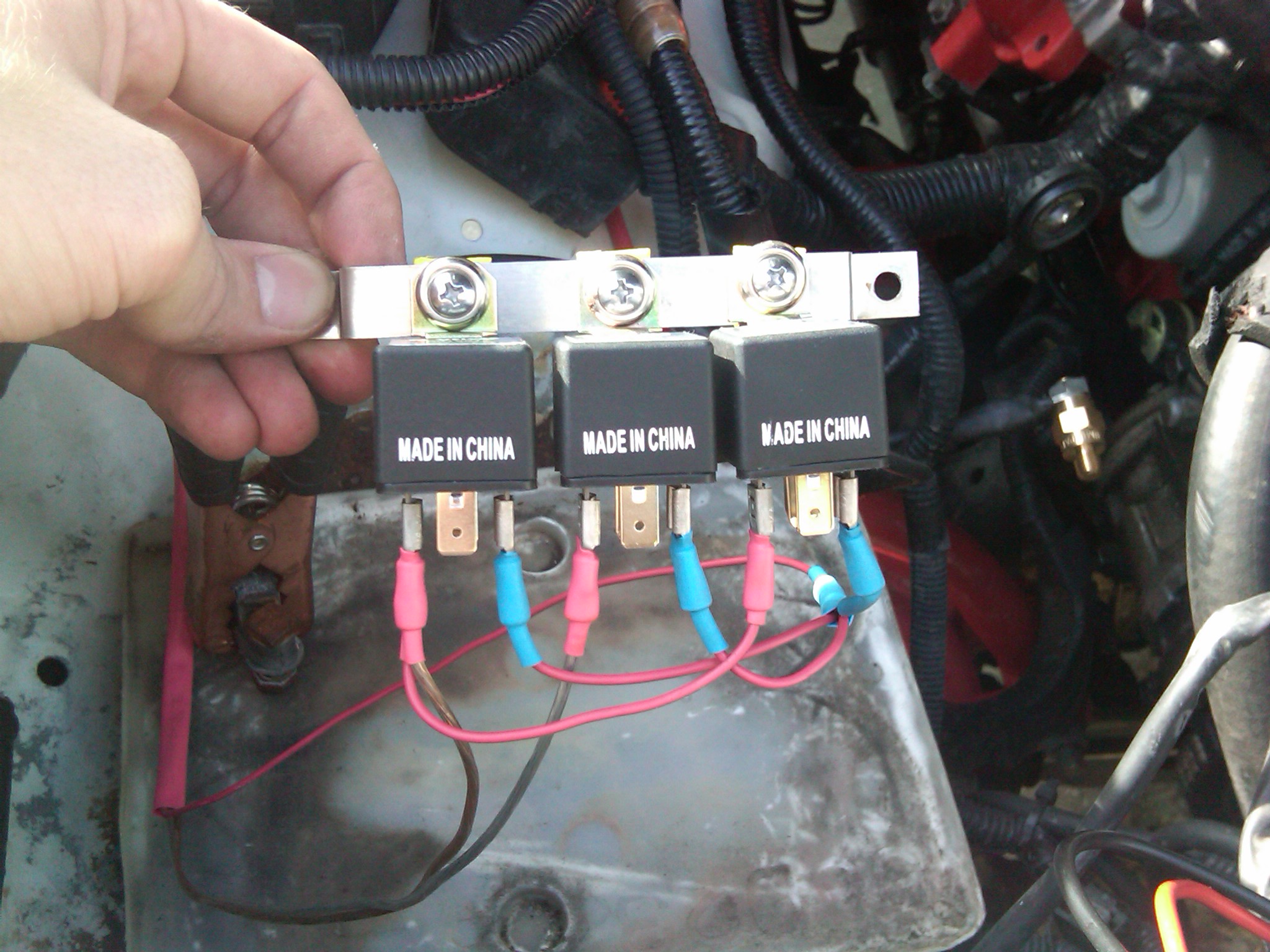
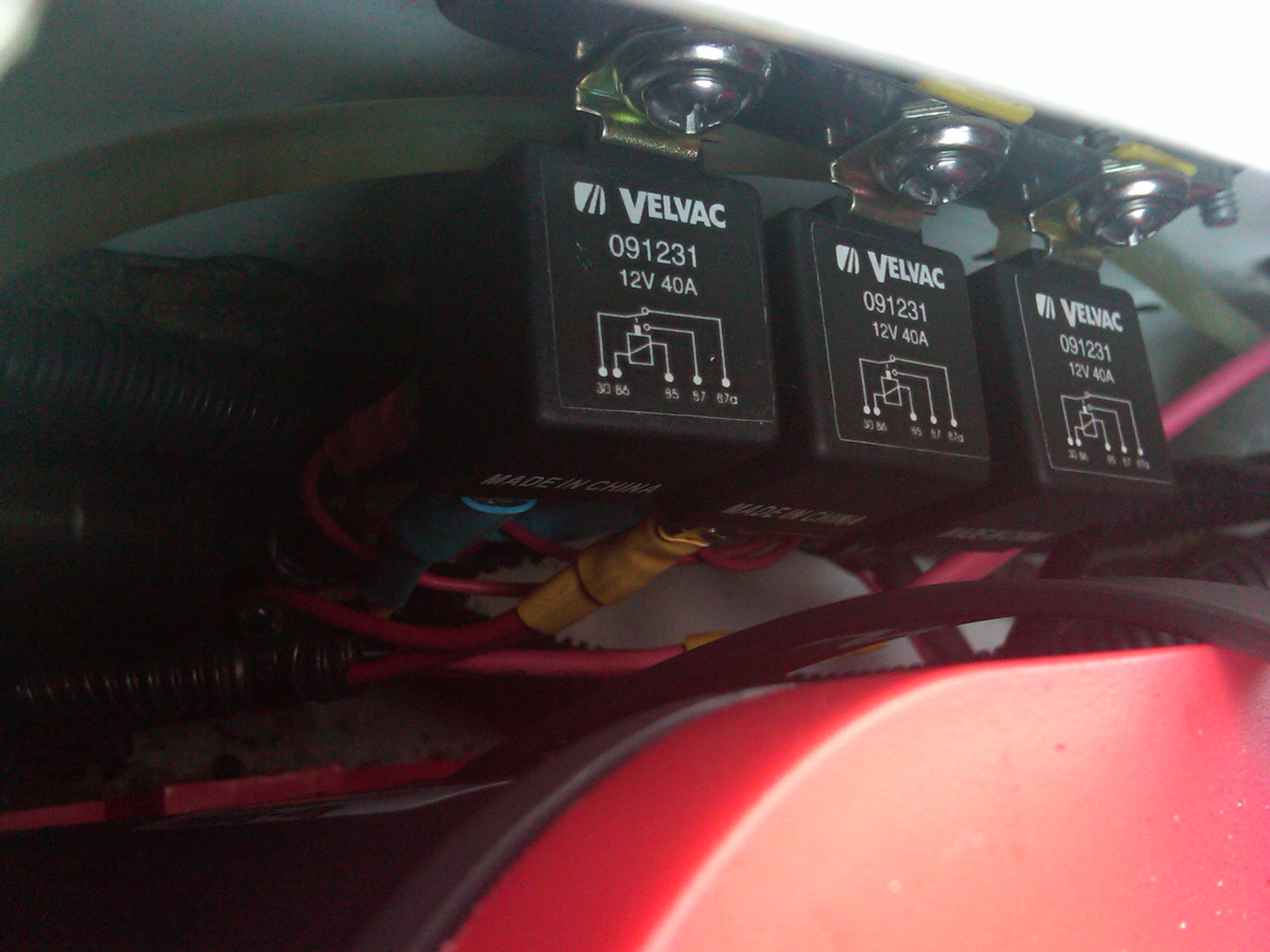
fabbed a relay mounting bracket out of a large hose clamp; worked like a charm
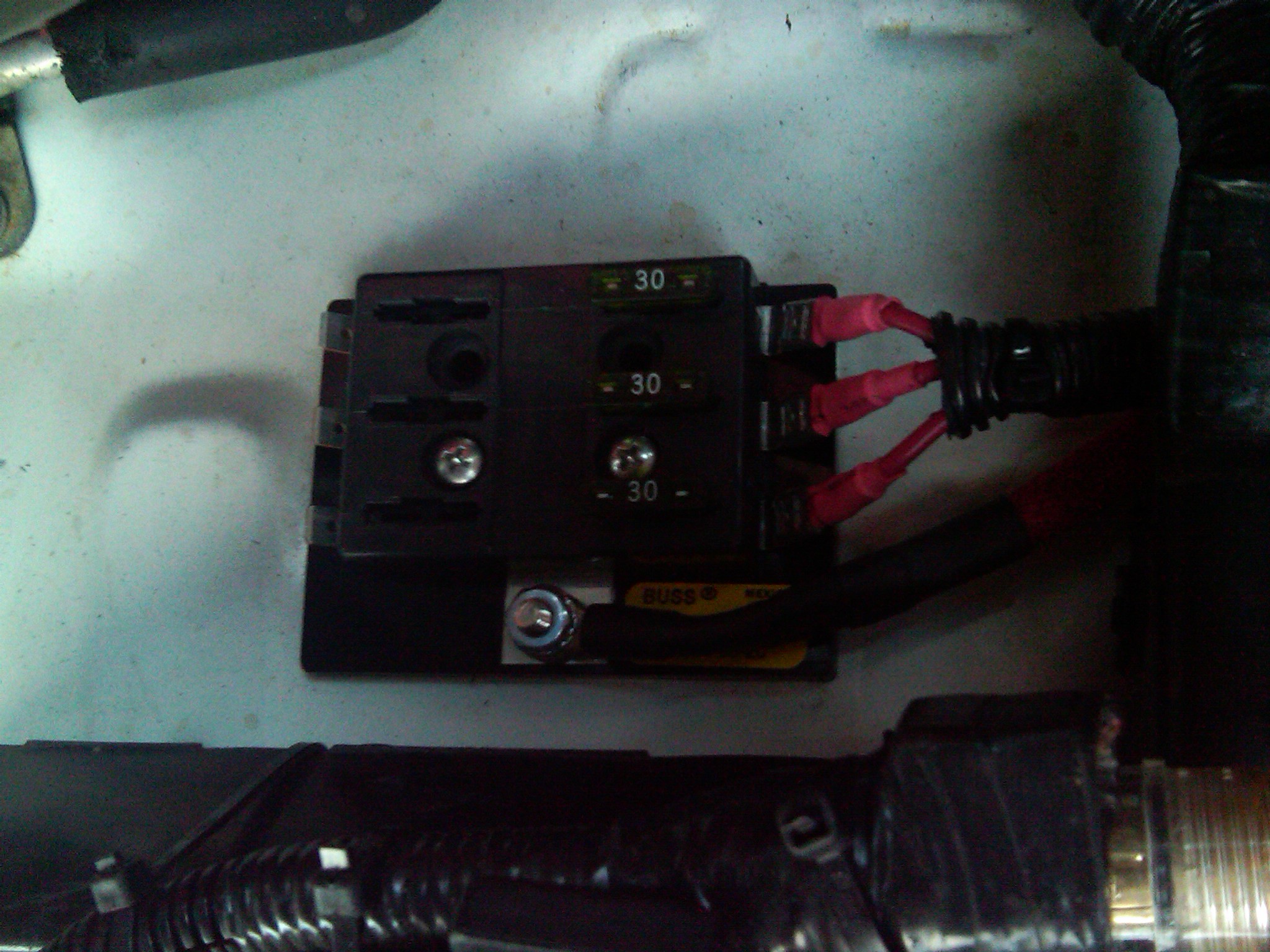
mounted the fuse block
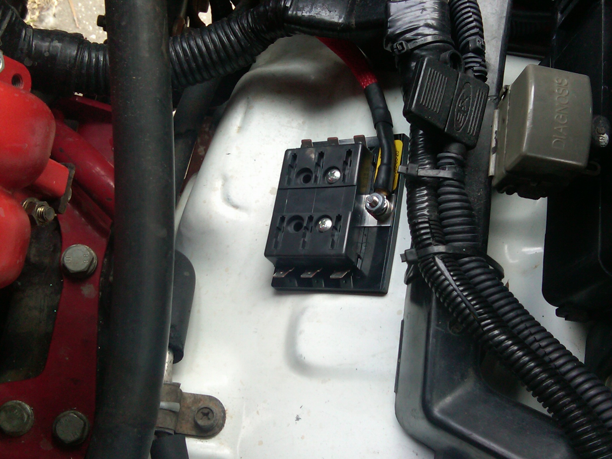
ran the wires from the fuse block, and from the original headlight socket, with the diode in bewteen the two leads from the original plug
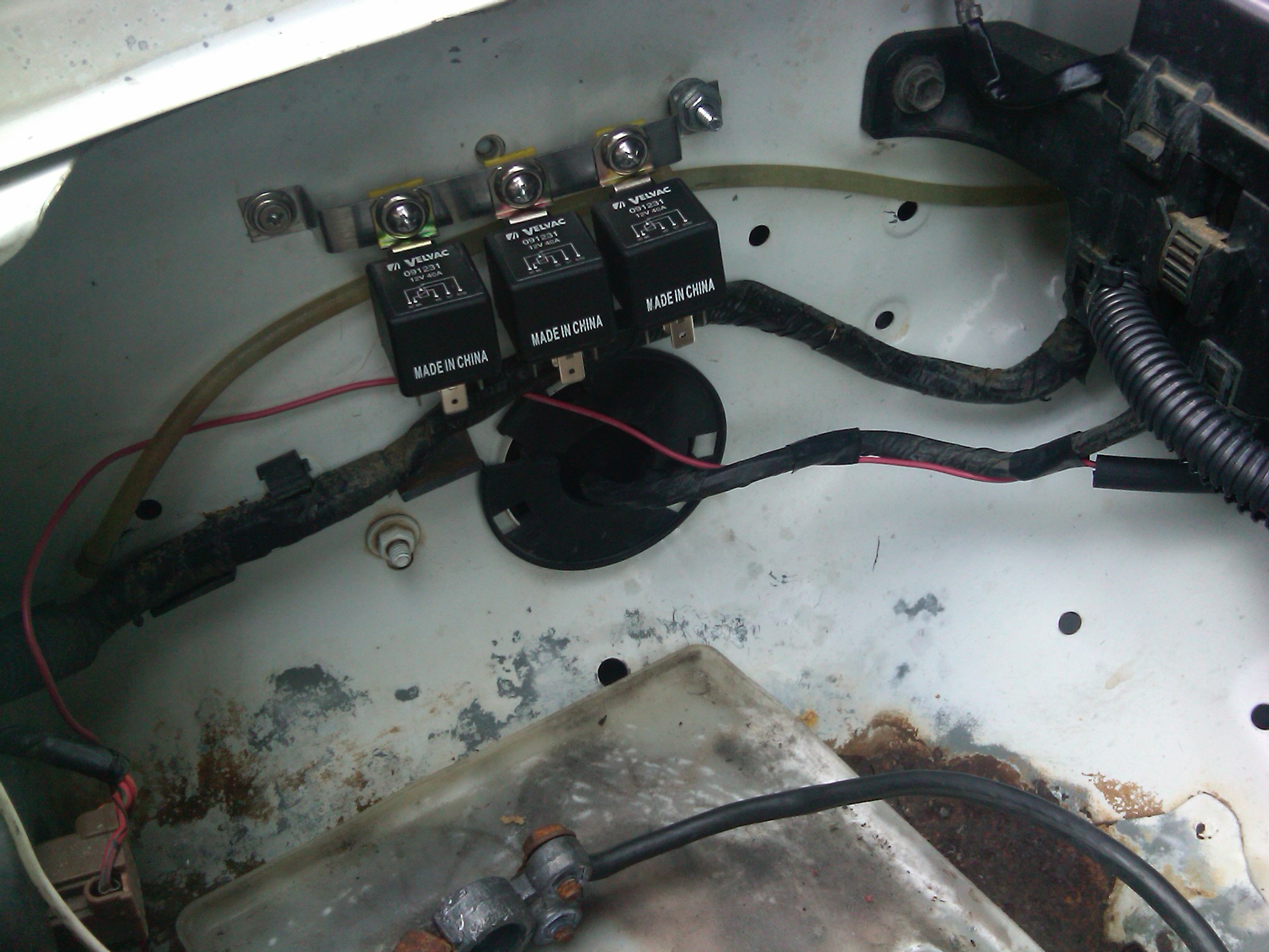
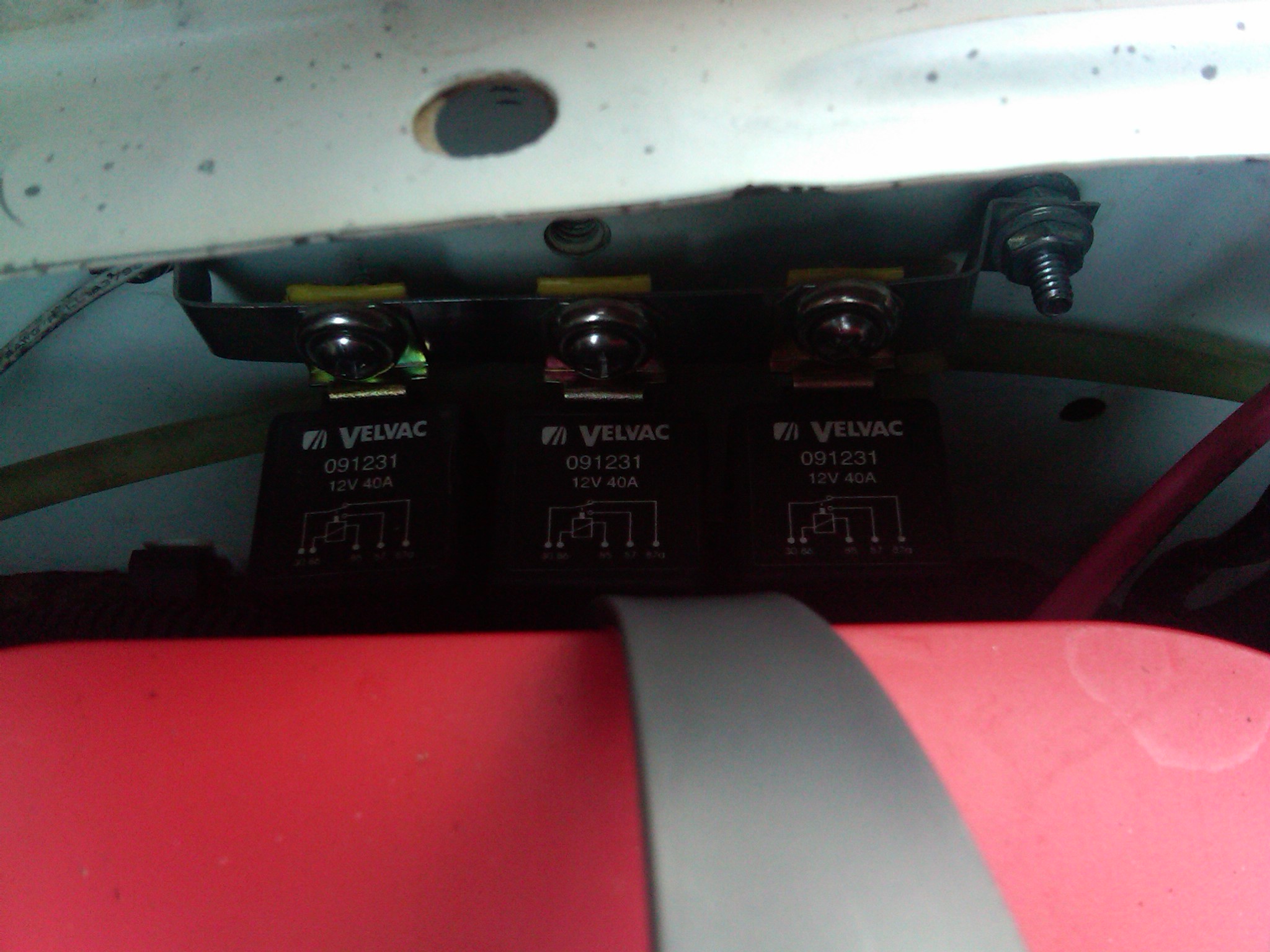
and found a suitable place to mount the realy assembly, right on the inner fender behind the battery
ran the new headlight plug wires, then dropped the battery in to make sure there was plenty of room still
threw some fuses in the fuse block
and everything works right!
although I don't have any other pics on the process... I was kinda in a hurry as I was loosing light...
and I realise I didn't use actual relay sockets wire in; I just used the spade connectors. I've used them just like this in the past wirh no problems; if I do get corrosion issues, I've got plenty of extra wire to cut the spades off and hard-wire in some sockets instead
fabbed a relay mounting bracket out of a large hose clamp; worked like a charm
mounted the fuse block
ran the wires from the fuse block, and from the original headlight socket, with the diode in bewteen the two leads from the original plug
and found a suitable place to mount the realy assembly, right on the inner fender behind the battery
ran the new headlight plug wires, then dropped the battery in to make sure there was plenty of room still
threw some fuses in the fuse block
and everything works right!
although I don't have any other pics on the process... I was kinda in a hurry as I was loosing light...
and I realise I didn't use actual relay sockets wire in; I just used the spade connectors. I've used them just like this in the past wirh no problems; if I do get corrosion issues, I've got plenty of extra wire to cut the spades off and hard-wire in some sockets instead
Last edited by iamsuperbleeder; 01-17-2010 at 04:23 PM.


