When you click on links to various merchants on this site and make a purchase, this can result in this site earning a commission. Affiliate programs and affiliations include, but are not limited to, the eBay Partner Network.
I have been searching and researching for the available options and custom ideas for a better idler arm. It seems the best on the market is the total chaos option. At $450 to 500 bucks it's relatively expensive but the alternative of breaking several $100 options is not better, making the TC option worth it.
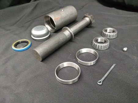
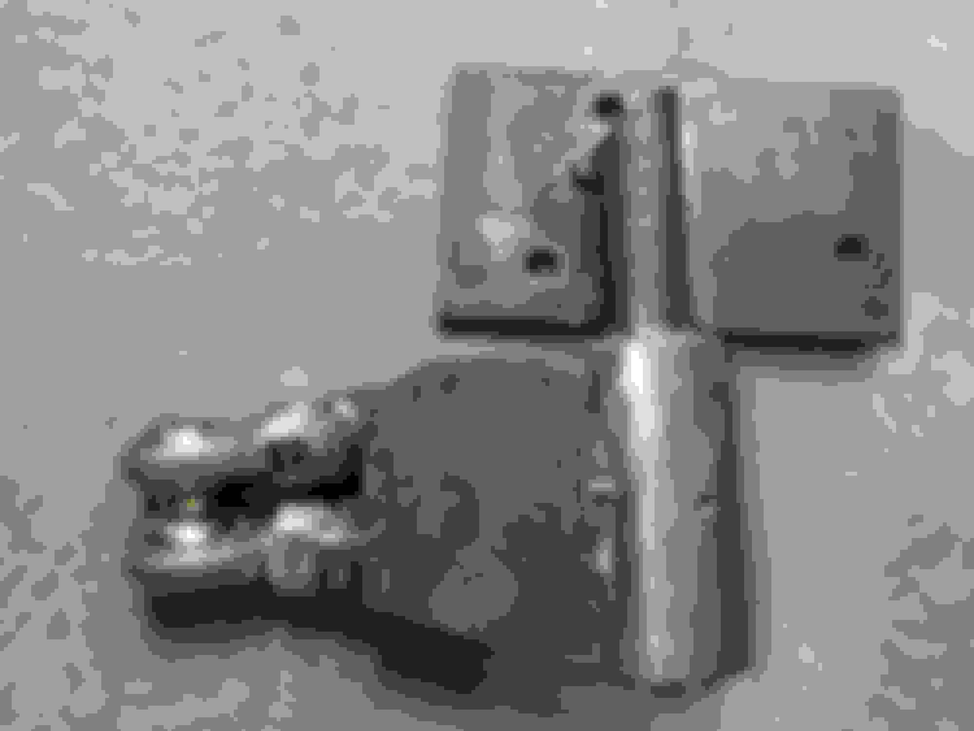
Well, as I have been looking into this I kept picturing a design utilizing a heavy duty trailer spindle. I was trying to avoid building my own as time is difficult to come by. However, since I didn't find what I am looking for, I decided I will give it a try. I didn't find a trailer spindle that made sense dimensions wise but I settled on the next best option. I purchased a tire carrier hinge spindle kit. I was about to purchase $120 heavy duty setup (4x4labs), but I decided since this has a chance of not working out, or at-least the 1st iteration not working out, I should find something cheaper to experiment with. I purchased this from amazon, about $60 shipped. If I can make the design work and end up needing a more heavy duty item, I will gladly spend more money on the 4x4labs kit. I would like people's input on this idea. Once the spindle gets delivered I will regularly update this thread to document the process. If this has been done before please share it!
I wanted to add that since I put my 34 inch tires on there I have been bending my idler arm and the abuse to the overall steering system has exponentially increased.
I purchased some steel and a heim joint today. I have no experience with heims and I am finding out that they should definitely be replaceble. I have to change my design slightly to accomodate. Lol This is a 3/4" heim. I loved how beefy it is. But i i hav to get the male version and threaded insert to make it adjustable and replaceable.
I think i will get some hot glue and cardboard out to mock one up and make sure it clears the frame.
I know most people do a build and then share it here. I like to share the idea and process as sometimes people will have some excellent input that improves the design.
The tapered roller bearings will certainly increase the stiffness of the rotation and axial directions this pivot needs for robust performance.
You might take a look at the Kit that Northwest Off-Road sold in the 90's which attempted to tie the arm to the top and bottom of the OEM shaft.
This was a very real weakness in the SCORE 7S pick-up that I was associated with in the 80's.
The 2WD arm was ridiculous when compared with the 4WD one.
Bridging the top and bottom of the arm to the ends of the housing was the only robust solution to keeping the 31X10.5R-15s and 12" of travel race worthy.
So in a nutshell incorporate that as best you can and don't rely on only the bending strength of the shaft to do the business.
Thanks for the reference and your thoughts Andrew. What I have in mind is supposed to be far stiffer and hopefully unbendable. I should not need to brace it. But untill i build and test I guess I cant be sure
I am anxious to start actual fabrication work on this! I am supposed to get the spindle kit today and I have the day off of work tomorrow!
Meanwhile, I got some more parts in. I sketched an idea in the case I wanted to use a ball joint instead of a heim joint. I may as well share that too. It's a rough draft but the idea is there.
I have the thread insert for a male thread Heim
I have the 3/4" Heim joint
I have the 1" ID tube that the thread insert nicely fits in
The idea it turns out is very similar and probably influenced by the thread I shared in one of my earlier posts. Later I found out I had even posted in there a long time ago. lol. My memory is terrible! https://www.yotatech.com/forums/f116...s-info-281631/
Where azdesertrunner used two heim joints for strength I am going to use one heim joint but a larger one. And for bending stiffness I will be using triangular guesetting. I initially sketched mine to have the bearing assembly of the spindle to be the part I connect the idler arm and the other end was to be welded to the support bracket connecting to the frame. Now I am not sure which is the correct way, once I get my hands on the spindle I will figure it out.
Incase I use ball joint not heim Heim setup side by side with stock setup
Well, I am not afraid to admit when I was wrong about something
And, I had misunderstood azdesertrunners use of two heim joints. I did write earlier that I don't have any experience with heim joints and that showed in my first version idler arm. Basically the single heim joint allowed too much rotation. Suffice it to say I have learned a lot and am grateful for azdesertrunners thread as it definitely helped having it as a resource.
In the end my design is very similar to his. I did stick with the spindle rotating part hanging down because it provided a better platform to weld the heims to and the support gusset. This has a drawback as it does hang down several inches lower than stock and it is possible that it hits a rock or something on the trail. I will just have to add some protection.
I tacked the first tube and held it in place for fit test. I am using 3/4 " heim joints. This presents a little problem as the holes are 3/4" and the bolt on the stock idler arm is .45". I got 3/4X1/2" sleeve bearings and grade 8 bolt. I decided to get 3/4 X 5/8" sleeve bearings and drill the center link hole out a bit. This is because the hole is tapered for the ball joint and I believe this hole will get loose through the years if only the end is actually snug against the 1/2" bolt. Test fit with some mock up gussets. Tested lock to lock. I should add that I took this opportunity to lower the idler arm about 2 inches. I believe this will further help to stabilize the linkages/steering and save the boots life. I do have to get a drop pitman arm though. After playing around with the setup in the previous pic, I realized my error with the design of one heim. It was a very easy design change to make though, had just the right space to add another heim. Clearance check again Here you can see the simple mount. And gusset. I am using 1/4" steel. I had to cut the spindle top to be able to mount the spindle as high as I need it and clear the bolt. I could have made my arms another 3/4 longer and move the whole thing further back on the plate. The spindle would clear the bolt. BUT, I decided the arm being short is important. I did have to make sure radius was enough not to mess up the steering geomtery. Also, I decided a gusset on one side was more than enough. From the other side The sleeve bearing. I need another, this one is only 1" long. Installed and tested. And, it looks awesome. Nice and beefy!
All in all I am in about $160 and half day of my time. You probably noted that I only tacked everything, that is because my welder is not powerful enough to give me nice deep welds on 1/4' steel. I need to borrow or rent to finish it.
I also completed installing all new tie rods. I tested my stabilizer shock and it is in great condition.
I took some before videos of how much movement there was in the steering system. Once I have the new idler arm totally welded up and installed, I will do a test again and share the two videos.
I can tell you now this is much, much stiffer!
Thanks to this forum for imparting a lot of wisdom and knowledge that helped me get a good working design!
To build and sells these things I would have to put it through it's paces, then redesign and rebuild and on and on until it's perfect. I wouldn't want to build a product with flaws.
That leads me into some of the thoughts I have been having about this. I haven't welded it up yet it's still just tacked. I increased the stud bolt from 1/2 to 5/8 grade 8 and I need a 5/8 bit to drill out the drag link end (remember this is a tapered hole I want to make straight.
I was trying to understand better why the single heim didn't do it's job. I believe it is because the rest of the steering system. The entire center link or drag link is connected with ball joints. This allows for rotation of the center link, this rotation creates unwanted movement. So I was trying to understand why would the idler arm and pitman arm have ball joints. To me it seems these joints should only allow rotation perpendicular to the ball joint center axis and not in all the other directions. If this was the case then the center link would not rotate and it will eliminate a bit of the movement in the system.
I am almost sure I am missing something. Before I go and finalize everything I want to understand this. Otherwise, I want to modify my pitman arm to use a heim joint as well.
Good idea taking the roll axis away from the drag link with the pair of rod ends. I am quite sure Toyota put that roll axis in the steerings design to allow for the steering box sector shaft and idler shaft to still rotate without binding when the pair are not dead parallel to each other when mounted on the sides of the frame rails. As long at you allow for one or the other of the pivots at the steering box or the idler to allow for the drag link to rotate ever so slightly that should provide enough freedom of movement to stop things from binding up at full lock. But if the box and idler shaft can be aligned to each other as the bolts are fixed to the frame then this issue goes away. However the tolerance associated with the relative axis of the two components will be hard to meet in getting this sorted. If you do get the pitman arm and idler arm pivots super snug than the drag link would benefit from having a central bearing that allowed its two halves to twist independently but without any axial slop/play being a desired constraint and also able to manage the buckling strength needed to be like a solid steel part.
I hope the bearing races can be removed from the housing so you can weld it up and not take the bores out of round. TIG it as this will provide the best control of the heat into the steel. Mig weld then flux-core or stick-arch as a last resort for welding choices would be my take.
Aside from flipping the whole thing upside down and welding an arm to the shaft would have been my approach as the housing to the frame has a better flow in analysing the strain energy. So, now having stated this; how large is the shaft diameter inside the housing at the bearing race? The OEM stuff depending on the brand have diameters that are �.703 - �.786". If your spare tire pivot housing's shaft is heading north of 1.00" then this is good stuff because the shear area goes up as the square of the diameter. In addition the bending stress goes down because of the larger size but the alloy needs to be known in order to make a decent estimate for fatigue strength. It is the reversed bending stress induced into the idler arms shaft that snaps it given enough loads and cycles with big rubber and wheels. All that gusseting to tie the arm to the housing buys you nothing if the shaft is the smallest in crossactional area as the strain energy is dissipated into the frame mounting. My concern would be that although the shaft is bigger the actual pivot point is further away from the underside of the frame and that would by definition increase the bending moment in the shaft. The distance is calculated from the middle of the two bearing in the housing to the point where your shaft is welded to the plate that bolts to the frame. Analysing all of these factors is how Toyota designed it the way they have it. It is just that the shaft should probably be that same size as the sector shaft on the steering gear box to keep the relative deflection the same across the steering linkage. Now a gutted right hand drive steering gear box would be a sweet answer to this problem.
Nice work and great pictures and thank you for sharing your efforts. Just be very careful as you sort out this design change. I had a moment were I had replaced the ball joints to the drag link and tie rod on my P38A 4.6 HSE Range Rover. They were made in India I later discovered and gotten them from a jeep aftermarket company on the internet. They were the correct taper and and general size. I had tightened the castle nut to Land Rover specification and 6 months later the entire nut and threaded portion of the tapered shaft left the steering linkage. Fortunately the drag link and ball joint fed into the steering arm on the top passenger side spindle assembly so gravity kept it in the taper. It was only after I had driven it home from work that evening that I discover why the steering didn't feel exactly right. I cannot emphasize enough that steering components need to be of the correct alloy composition and design because if that taper had hopped out of the arm the steering gear would have been detached from the front wheels. When I got home I lifted it out without any puller or tapping or a hammer. It just lifted out really a scary realization.
Good idea taking the roll axis away from the drag link with the pair of rod ends. I am quite sure Toyota put that roll axis in the steerings design to allow for the steering box sector shaft and idler shaft to still rotate without binding when the pair are not dead parallel to each other when mounted on the sides of the frame rails.....
Thanks, but most of the credit goes to azrunner who's thread helped me put my design together
I can tell you have a background in engineering to some degree, I appreciate the lingo. I have an MS in Structural engineering and studied mechanical eng as well in undergrad . I did in fact consider the various forces and how they would flow through the joints to the arm to the spindle and to the frame. I tried to eliminate any eccentric forces and support bending forces to take the pressure out of the welds. Like I said, there is probably a lot of room for improvement in the design. In fact I believe now that the heim joint is not the best option for this application. I believe the geometry should be bang on (and alignment of pitman arm and idler arm) and a sleeve bearing should be used which only allows rotation in one fixed axis.
Yes, the bearings and seals will all be removed prior to welding. I am looking for a shop nearby that can do Tig welding for me because I don't want to put any more heat into the bearing housing and spindle than I have to. So I definitely agree with that.
The ID of the spindle shaft is 1.0125 inches I believe. I think it is sufficiently strong enough that it will not be loaded to anywhere close to it's elastic limits.
I am not gona buy cheap parts for sure. You almost always end up paying more in re-doing the work too soon. I purchased proforged's tie rods and they seem to be of good quality. There really aren't too many options other than OEM.
Toyota designed it the way they did because of engineering but also cost savings. I really don't like the ball joint steering system
I took some time trying to decide how I am going to weld this up. In the end, I decided to get a bigger welder. So, I did! World of a difference, I wish I had bought this a long time ago.
I put down a couple of short beads to make sure it feels about the same as the other welder. Surely it was different, but I was excited to get my idler arm installed!! I should have practiced on heavier material. In the end I have a great strong weld but the first couple beads came out funky looking. I dont like to grind my welds down for 2 hours to make it
seem like I welded better than I did. lol.
At the end of the post make sure to check out the before and after videos. I simply put the passenger side up in the air and with my hands tried to force the steering system to move. Honestly, the difference is surprisingly dramatic and more than I expected. Mostly because stock is soo terrible. lol.
First, I had to go to home depot and get a three prong 240 volt outlet. This is what I had installed previously. Had to drill out the taped 1/2" hole to 5/8. This bolt is actually under lots of load in this design. Grade 8 - 5/8" bolt installed. After a few beads I got the hang of the new welder. All welded up and a very glossy black paint job completed. I added two gussets to the top bar. You can kind of see in this pic. Checked clearanced. more checking. And I think it looks great!

 01-31-2020, 01:08 PM