
22R Rebuild

 03-07-2010, 05:36 PM
#304
Registered User
Join Date: Jan 2010
Posts: 38
Likes: 0
Received 0 Likes
on
0 Posts
breaking in an engine? talk to 10 different builders and you are gonna get a few different answers. write it all down, and use what seems most common? or take the advice one one you trust.........then blame him when you over rev it and burn something up lol
ill have my 22R built in a few weeks, and offer my 2 cents on breaking it in then.
ill have my 22R built in a few weeks, and offer my 2 cents on breaking it in then.
03-07-2010, 06:38 PM
#305
Registered User
Thread Starter

To resize my pictures I either use a script I wrote that uses imagemagick tools, or I manually crop and resize in GIMP. My operating system is Linux. Irfanview is a neat, small, free image viewing/manipulation application for Windows users.
I'm using a new cam. To break the engine in I'm thinking I'll probably run it 15-20 minutes slightly above fast idle while burping air out of the cooling system and watching for leaks or other problems. Shut down, recheck head bolt torque, adjust the valves and change the oil.
Then start it back up, adjust the timing (or should I do that during the first run?), let it warm up a few minutes at fast idle, and go for a drive. Do multiple rounds of hard acceleration followed by decelerating using engine braking. Essentially, punch it and then get off the pedal.
Does this sound about right?
Because my engine is sitting outside on a pallet we've had some of the heaviest rain downpours today I've ever seen. I have help available again tomorrow, but it's not looking like the weather will cooperate. We'll see in the morning. I don't know when anyone will be free after that to help me get this thing in.
I bought a load leveler at Harbor Freight today. 20% off a single item coupons for use in their physical stores are available continuously. Here's a regularly updated thread dedicated to HF coupons: http://slickdeals.net/forums/showthread.php?t=1276399
Last edited by flyingbrass; 03-07-2010 at 08:53 PM.
03-08-2010, 06:16 PM
#306
Registered User
Thread Starter
The weather let up enough this afternoon to allow another try at installing the engine. I removed the valve cover and hooked up the new load leveler. Jacked the tranny up to about where it was when the engine came out.
We had the engine in the bay and angled about right. It was looking like it should go when we discovered the back part of the load leveler was contacting the heater hoses, preventing the engine from moving back. Even disconnecting the heater control valve and twisting it out of the way didn't buy enough clearance. #$%*$ #@#&!^*#%#@$^&*!!!!
The original rigging:

We took the engine back out, took off the shackle that was on the chain at the rear hook, and lengthened the chains between leveler and engine hooks. Fearing this may not allow the engine to raise high enough, we used the shackle to connect the leveler higher up on the hoist chain. A picture explains it best. The front chain should have been shorter, but the engine lifted high enough to fit into the bay, so good enough. The leveler made adjusting tilt easy.

A swivel added somewhere in the hookup would be very helpful because the engine wants to rotate. We ended up turning the hoist pretty far to the side to help compensate:

It still wasn't easy, but finally the engine stabbed in. The bottom of the bellhousing/engine made full contact. The top had about a 3/8" gap even after putting some bottom bellhousing bolts in and lowering the tranny and engine. Installing the two evil top bolts closed the gap. We got them in using swivel joints and a stack of extensions. Tight fit, especially on the driver's side, but we managed without lowering the tranny.
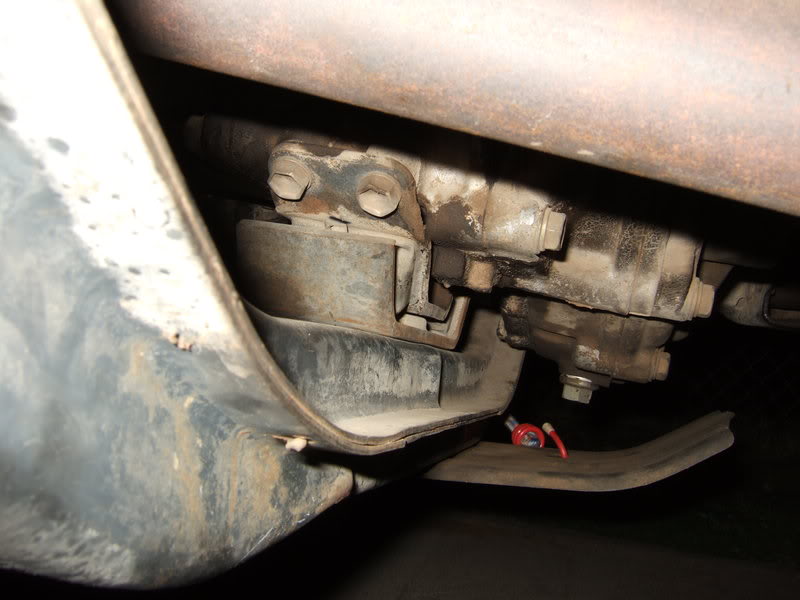
A problem remains. The motor mounts don't line up. The driver's side is the worst.
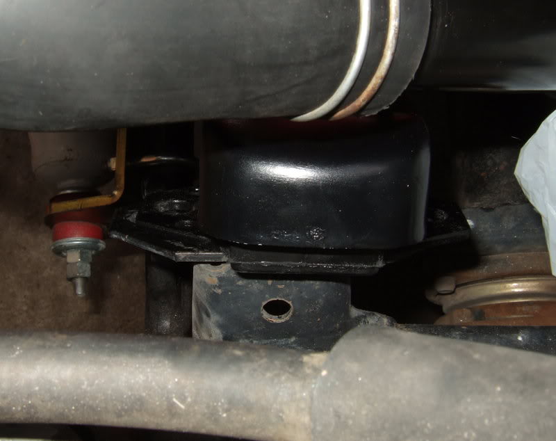

Notice how my old driver side mount is squished over as though it didn't line up very well either.
The passenger side is off some too, but not as as much.
Any suggestions how to deal with this?
We had the engine in the bay and angled about right. It was looking like it should go when we discovered the back part of the load leveler was contacting the heater hoses, preventing the engine from moving back. Even disconnecting the heater control valve and twisting it out of the way didn't buy enough clearance. #$%*$ #@#&!^*#%#@$^&*!!!!
The original rigging:
We took the engine back out, took off the shackle that was on the chain at the rear hook, and lengthened the chains between leveler and engine hooks. Fearing this may not allow the engine to raise high enough, we used the shackle to connect the leveler higher up on the hoist chain. A picture explains it best. The front chain should have been shorter, but the engine lifted high enough to fit into the bay, so good enough. The leveler made adjusting tilt easy.
A swivel added somewhere in the hookup would be very helpful because the engine wants to rotate. We ended up turning the hoist pretty far to the side to help compensate:
It still wasn't easy, but finally the engine stabbed in. The bottom of the bellhousing/engine made full contact. The top had about a 3/8" gap even after putting some bottom bellhousing bolts in and lowering the tranny and engine. Installing the two evil top bolts closed the gap. We got them in using swivel joints and a stack of extensions. Tight fit, especially on the driver's side, but we managed without lowering the tranny.
A problem remains. The motor mounts don't line up. The driver's side is the worst.
Notice how my old driver side mount is squished over as though it didn't line up very well either.
The passenger side is off some too, but not as as much.
Any suggestions how to deal with this?
Last edited by flyingbrass; 03-08-2010 at 08:23 PM.

 03-08-2010, 07:51 PM
#310
Registered User
Join Date: Jan 2010
Posts: 38
Likes: 0
Received 0 Likes
on
0 Posts
ok im a bit late on the suggestion for the engine stab. but ill say this for next time. ive put mine in twice over the years with exactly same cherry picker. short chain on intake side, short chain on exhaust side. two guys on engine and one on floor jack working tranny height and it would go in with valve cover on..........
last tiem with engine i had to loosen motor mounts bolts and then take a pointed prybar to get them over to line up. put a bolt in a few turns then work on next one. then slowly tighten them up up. like u would for torquing a head. good luck and once agian great pics
last tiem with engine i had to loosen motor mounts bolts and then take a pointed prybar to get them over to line up. put a bolt in a few turns then work on next one. then slowly tighten them up up. like u would for torquing a head. good luck and once agian great pics
03-09-2010, 01:31 AM
#311
Registered User
Join Date: Jul 2009
Location: Eastern NC
Posts: 832
Likes: 0
Received 0 Likes
on
0 Posts
When I put new eng mounts in mine, the tranny mount seemed good also. but when I lowered the eng down the mounts did not line up. I fought with it for two days before loosening the tranny mount. once I did, the eng mounts slipped right in, and the drive train was in good alignment. then I went back and tightened the tranny mounts. I am talking about the tranny mount bolts that go up through the crossmember, not the ones into the tranny itself. good luck.
03-09-2010, 05:18 AM
#312
Registered User
Join Date: Oct 2009
Location: NW Phoenix
Posts: 134
Likes: 0
Received 0 Likes
on
0 Posts
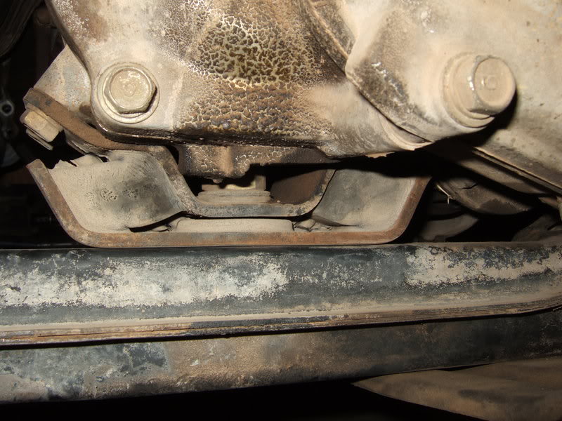
I do see wiggle room on that Trans mount. It looks as if it could move forward 1/4 to 1/2 inch. Notice there is more of an overhang of the mount on the rear of the crossmember? Loosen the 1 bolt on the trans mount at the crossmember, move engine/trans/case forward as 1 unit just far enough to secure the motor mounts. Resnug the trans mount bolt, and job well done.
Last edited by Staceman1; 03-09-2010 at 05:23 AM.
03-10-2010, 04:13 PM
#313
Registered User
Thread Starter
You mean the big bolt in the middle of the trans mount that would be hard to get a wrench on with everything together? It holds a circular piece underneath. I tried everything except that.
To gain play, I loosened: 4 12mm bolts in the trans mount, crossmember bolts, engine mount to block bolts. The nuts on the mount studs were already loose. Got underneath and used my legs in an attempt to shove everything forward. Also tried to knock the trans mount forward using a block of wood and hammer. Made sure the crossmember itself was as far forward as it could go. Pried the mount brackets on the block forward. The engine was mostly supported by the hoist through all this (hoping it would be easier to shove forward).
None of that did anything. I got the bolts in by prying the rubber parts of the mounts forward. The passenger side didn't need much. The driver side required a lot -- enough that it can't be good for the rubber to be stressed like that. However, the old driver's side mount was similarly mushed over.

I wonder if the dent in my crossmember is partly responsible.
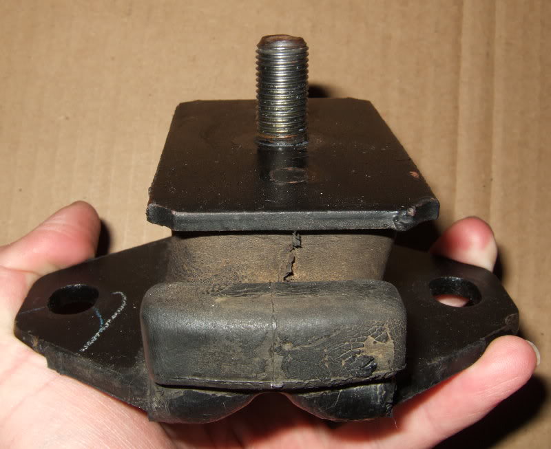
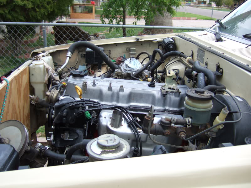
As shown before, the new mounts are taller than the old ones (see this post). Maybe too tall. I had a very difficult time getting the valve cover on past the heater hoses. At first I didn't think it would go at all. Look how nose high the engine sits. Is that normal for new mounts? Do they start like that but quickly settle in? Maybe they aren't the right ones.
I'm thinking the fan will be too high to fit in the shroud. I plan to check that next.
To gain play, I loosened: 4 12mm bolts in the trans mount, crossmember bolts, engine mount to block bolts. The nuts on the mount studs were already loose. Got underneath and used my legs in an attempt to shove everything forward. Also tried to knock the trans mount forward using a block of wood and hammer. Made sure the crossmember itself was as far forward as it could go. Pried the mount brackets on the block forward. The engine was mostly supported by the hoist through all this (hoping it would be easier to shove forward).
None of that did anything. I got the bolts in by prying the rubber parts of the mounts forward. The passenger side didn't need much. The driver side required a lot -- enough that it can't be good for the rubber to be stressed like that. However, the old driver's side mount was similarly mushed over.
I wonder if the dent in my crossmember is partly responsible.
As shown before, the new mounts are taller than the old ones (see this post). Maybe too tall. I had a very difficult time getting the valve cover on past the heater hoses. At first I didn't think it would go at all. Look how nose high the engine sits. Is that normal for new mounts? Do they start like that but quickly settle in? Maybe they aren't the right ones.
I'm thinking the fan will be too high to fit in the shroud. I plan to check that next.
Last edited by flyingbrass; 03-10-2010 at 04:20 PM.
03-11-2010, 02:53 PM
#316
Registered User
Join Date: Jul 2009
Location: hubert nc
Posts: 1,151
Likes: 0
Received 0 Likes
on
0 Posts
The weather let up enough this afternoon to allow another try at installing the engine. I removed the valve cover and hooked up the new load leveler. Jacked the tranny up to about where it was when the engine came out.
We had the engine in the bay and angled about right. It was looking like it should go when we discovered the back part of the load leveler was contacting the heater hoses, preventing the engine from moving back. Even disconnecting the heater control valve and twisting it out of the way didn't buy enough clearance. #$%*$ #@#&!^*#%#@$^&*!!!!
The original rigging:

We took the engine back out, took off the shackle that was on the chain at the rear hook, and lengthened the chains between leveler and engine hooks. Fearing this may not allow the engine to raise high enough, we used the shackle to connect the leveler higher up on the hoist chain. A picture explains it best. The front chain should have been shorter, but the engine lifted high enough to fit into the bay, so good enough. The leveler made adjusting tilt easy.

A swivel added somewhere in the hookup would be very helpful because the engine wants to rotate. We ended up turning the hoist pretty far to the side to help compensate:

It still wasn't easy, but finally the engine stabbed in. The bottom of the bellhousing/engine made full contact. The top had about a 3/8" gap even after putting some bottom bellhousing bolts in and lowering the tranny and engine. Installing the two evil top bolts closed the gap. We got them in using swivel joints and a stack of extensions. Tight fit, especially on the driver's side, but we managed without lowering the tranny.
A problem remains. The motor mounts don't line up. The driver's side is the worst.


Notice how my old driver side mount is squished over as though it didn't line up very well either.

The passenger side is off some too, but not as as much.

Any suggestions how to deal with this?
We had the engine in the bay and angled about right. It was looking like it should go when we discovered the back part of the load leveler was contacting the heater hoses, preventing the engine from moving back. Even disconnecting the heater control valve and twisting it out of the way didn't buy enough clearance. #$%*$ #@#&!^*#%#@$^&*!!!!
The original rigging:
We took the engine back out, took off the shackle that was on the chain at the rear hook, and lengthened the chains between leveler and engine hooks. Fearing this may not allow the engine to raise high enough, we used the shackle to connect the leveler higher up on the hoist chain. A picture explains it best. The front chain should have been shorter, but the engine lifted high enough to fit into the bay, so good enough. The leveler made adjusting tilt easy.
A swivel added somewhere in the hookup would be very helpful because the engine wants to rotate. We ended up turning the hoist pretty far to the side to help compensate:
It still wasn't easy, but finally the engine stabbed in. The bottom of the bellhousing/engine made full contact. The top had about a 3/8" gap even after putting some bottom bellhousing bolts in and lowering the tranny and engine. Installing the two evil top bolts closed the gap. We got them in using swivel joints and a stack of extensions. Tight fit, especially on the driver's side, but we managed without lowering the tranny.
A problem remains. The motor mounts don't line up. The driver's side is the worst.
Notice how my old driver side mount is squished over as though it didn't line up very well either.
The passenger side is off some too, but not as as much.
Any suggestions how to deal with this?
get a drill out and fix it..
or do one side at a time..
check to see if you dont have pre 85 engine mounts they did change slightly if i remember from a friend of mine told me he had a issue with new mounts
03-11-2010, 07:55 PM
#317
Registered User
Thread Starter
Apparently some 4 bangers in these years came with V6 mounts.
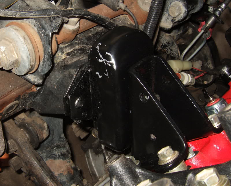
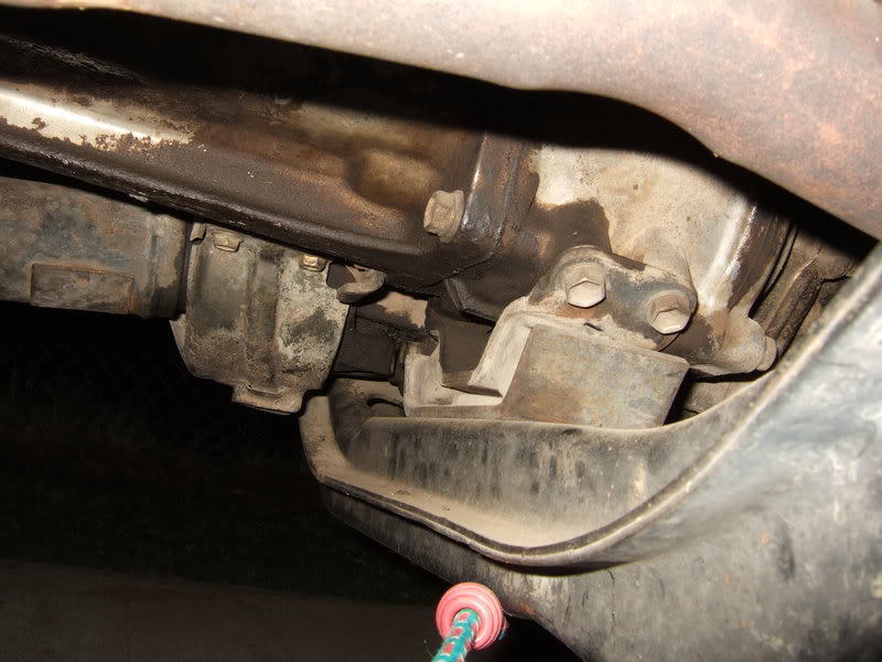
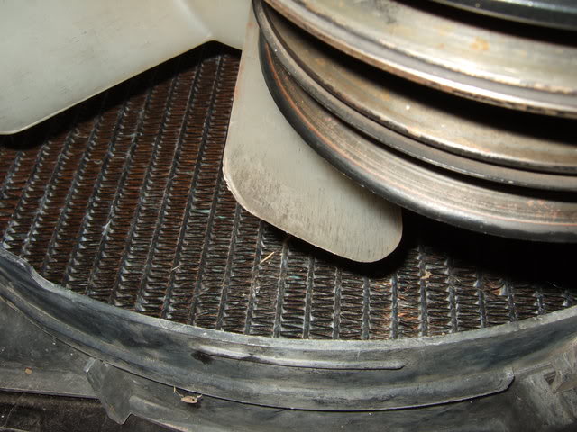
I didn't have much time today. I put the fan and radiator in with a few bolts to check the fit. The top gap between fan blades and shroud measured about 13/16". The bottom was about 1 1/4". The nose is up a tad, but far less than I had thought.
I tightened all the bolts on the motor mounts and everything else I had loosened in my attempts to move the motor forward. Got the starter, slave cylinder and clutch hose in before running out of light. Then realized I had forgotten a bellhousing bolt blocked by the slave. Doh! That's the way these things go. 3 bolts and the slave should swing away enough to get the bolt in.
Top fan clearance:
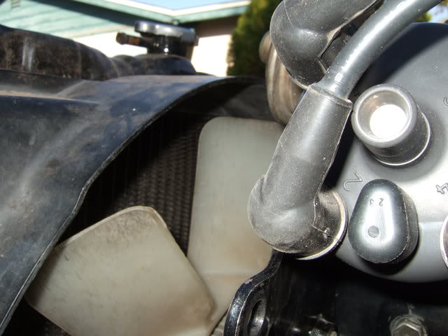
Bottom:
I didn't have much time today. I put the fan and radiator in with a few bolts to check the fit. The top gap between fan blades and shroud measured about 13/16". The bottom was about 1 1/4". The nose is up a tad, but far less than I had thought.
I tightened all the bolts on the motor mounts and everything else I had loosened in my attempts to move the motor forward. Got the starter, slave cylinder and clutch hose in before running out of light. Then realized I had forgotten a bellhousing bolt blocked by the slave. Doh! That's the way these things go. 3 bolts and the slave should swing away enough to get the bolt in.
Top fan clearance:
Bottom:
Last edited by flyingbrass; 03-11-2010 at 11:43 PM.
03-11-2010, 09:21 PM
#318
Registered User
Join Date: Jan 2010
Posts: 38
Likes: 0
Received 0 Likes
on
0 Posts
3 steps forwards two steps back, we've all done it over the years. something i learned first time i pulled my 22R: get 20+ envelopes, mark on each one what bolts go in them, intake, power steering etc. it makes putting the engine components back much easier.
keep up the good work, JJ
keep up the good work, JJ
03-11-2010, 09:54 PM
#319
Registered User
Thread Starter
I added a couple pics in above.
Amen on marking parts. I bagged, tagged and photographed most stuff. Pictures have been a huge help through this. I should have taken more.
Something I only figured out later is to snap some pics of the labeled baggie held up with fingers pointing were the bolts/nuts within it go. The reason for that being you might not remember later what you called those parts when you took them off. Same for vacuum lines. Take pictures with labels on before removing.
Last edited by flyingbrass; 03-11-2010 at 09:58 PM.
03-11-2010, 11:05 PM
#320
Registered User
Join Date: Jan 2010
Posts: 38
Likes: 0
Received 0 Likes
on
0 Posts
vacuum lines? you dont need no stinking vacuum lines with a weber lol
the one that kills me each time is the alternator bracket and power steering side brackets. one of the brackets looks like the hose should fit through it. like the 3 piece kindergarten puzzle i stare at for 30 minutes lol
you are doing a good job, keep it up. JJ
the one that kills me each time is the alternator bracket and power steering side brackets. one of the brackets looks like the hose should fit through it. like the 3 piece kindergarten puzzle i stare at for 30 minutes lol
you are doing a good job, keep it up. JJ


