When you click on links to various merchants on this site and make a purchase, this can result in this site earning a commission. Affiliate programs and affiliations include, but are not limited to, the eBay Partner Network.
1988 w/ 22re cranks but wont start after moving the wiring harness, removing heater
Hey everyone, I need some help as I am at a loss and looking for more threads to direct me.
I have a 1988 4runner that originally came with the 3.0. Prior to me purchasing it someone else put the 22re motor in it. It has always run great, and very reliably. This spring I put it into the garage to remove the heater core and heater components from inside the cab as they weren't working as it was and get some room in there, and while doing so decided to move the wiring harness that went underneath the fender outside so that it fed directly into the engine compartment on the passenger side. After completing removal and reconnecting all the wiring that I had disconnected the engine now cranks but won't start. It's like its not getting fuel...
Here is what I have done so far.
I have replaced the fuel filter and checked it for leaks
Turning the ignition to the 'on' position the pump starts up and pressurizes the line, originally when I removed the old filter I got sprayed pretty good because I did not depressurize prior to loosening the fittings, following replacement I loosened the bolt attached to the cold start injector and relieved pressure there as well and had gas spray out (the pump does run all the time so not sure if that is a problem as well, though that wouldn't have to do with it not starting I expect)
checked resistance on the circuit opening relay on the passenger side and it was within the ranges shown in the manual
checked resistance in the main relay on the driver side and it was within range
checked resistance on the water/thermo sensor on the front of the engine and it was within range
checked resistance on the cold start injector/time switch on the front of the engine next to the water/thermo sensor and it ready 79-80 ohms both ways (terminal to terminal, and terminal to ground),
checked resistance through the mass air flow sensor and all were within the specified ranges
the solenoid resister shown in the manual is not present and they have two aftermarket solenoids in place of it, I have checked connections on these and removed any buildup on the terminals (but have no idea how to check these otherwise)
What am I missing, is there something grounding out somewhere? Or is there some part of the heater core/heater/ac unit that has to be connected in order for it to start?
Currently my entire dash is removed as well as all the heater/ac components. And I can get photos of anything needed or take readings again to include if needed. Temp in the garage is about 70F.
Update: I put direct power from the battery to the cold start injector and it sprayed fuel so I know the cold start injector is good... but when cranking it doesn't get any power. I cleaned it up while out.
After rechecking resistance on the cold start injector thermo time switch it was giving odd readings so I will be replacing it as well as the temperature sensor while in there since that one doesn't cost much. Let you know how it goes. If that doesn't work I am down to a wiring issue or an ECU problem.
There is a crimp somewhere in loom under the intake manifold connecting ALL 4 injector negatives AND ECU pins 10 and 20 together. That could have been corroded/ broken when harness was moved. You can:
1) Inspect. and/or
2) Electrically test. IN order to reliably test electrically you need to access/disconnect injector connectors AND ECU connector then start probing for voltage/resistance.
Pin 2 of injectors always have 12V when IGN is on.
ECU pulses ground to #10 and #20 to turn on injectors.
Last edited by RAD4Runner; 05-18-2022 at 01:29 PM.
Thanks for the direction. I am trying to look at this now as I just put in the new cold start injector thermo time switch and the time sensor next to it and still getting the same results. Its got to be a wiring/ground issue as everything worked fine before moving the wires.
Originally Posted by RAD4Runner
There is a crimp somewhere in loom under the intake manifold connecting ALL 4 injector negatives AND ECU pins 10 and 20 together. That could have been corroded/ broken when harness was moved. You can:
1) Inspect. and/or
2) Electrically test. IN order to reliably test electrically you need to access/disconnect injector connectors AND ECU connector then start probing for voltage/resistance.
Pin 2 of injectors always have 12V when IGN is on.
ECU pulses ground to #10 and #20 to turn on injectors.
I am working on getting down to that wire crimp for all the negatives but am not sure if that would be it as I really didn't move any wiring in the engine compartment itself other than to rewrap what came out of the engine area.
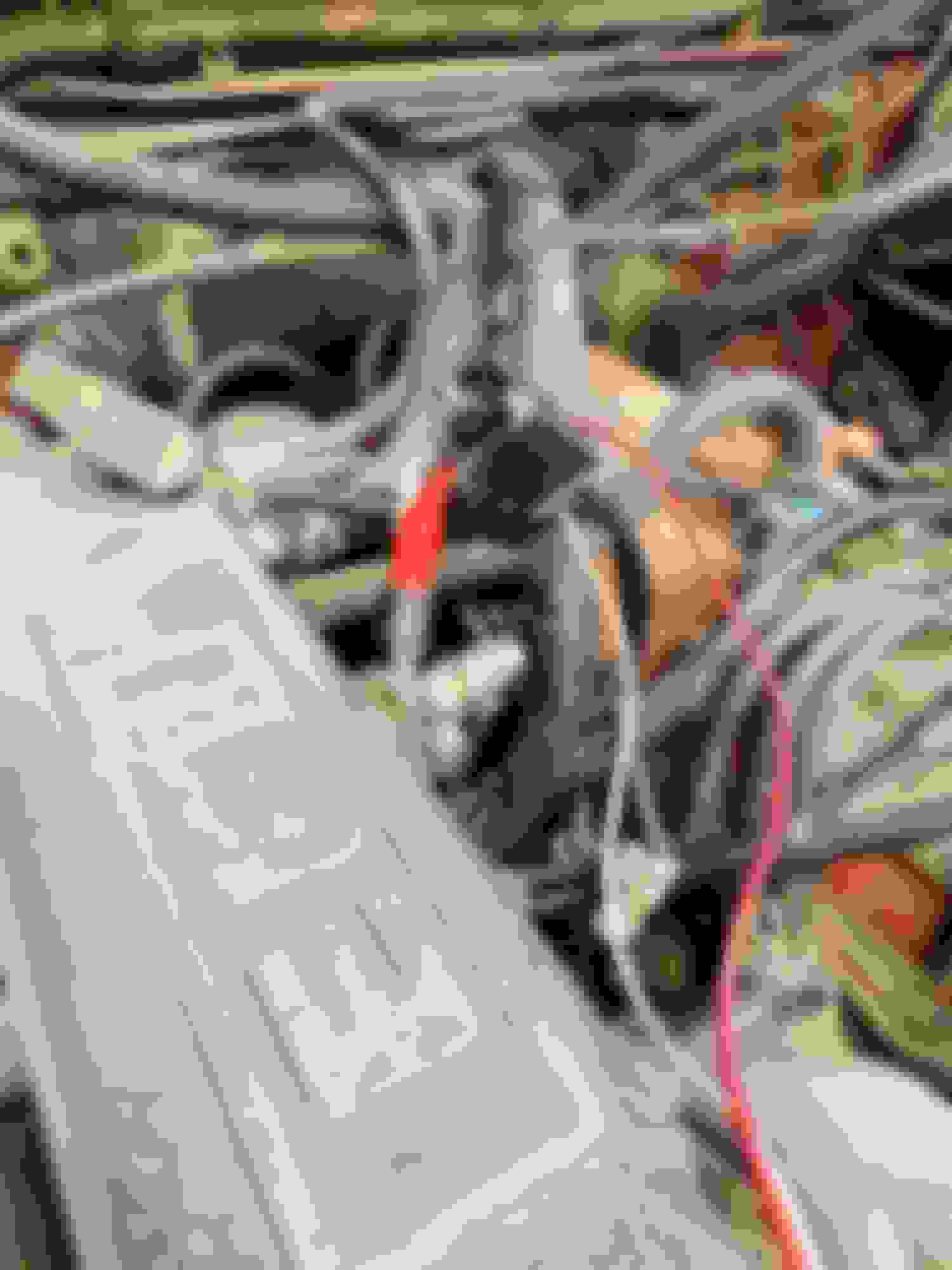
Here are some photos of the main harness that wasn't moved (containing all of the wiring leading to the cold start injectors, the injectors, and the sensors on the motor... and the one I did move (that was originally under the passenger fender). Also we did rewrap the wiring harness through the cab. Perhaps something is disconnected somewhere. I am getting to where I can measure 12v power to the injectors themselves by taking a few things apart.
I have also attached a short video of how it starts and runs with the cold start injectors bypassed hoping that someone can narrow down what connection might be loose who knows more than I do? If I leave it bypassed the engine waffles after a minute and seems to get too much fuel?
If I disconnect 12v power from the cold start injector directly then it runs for 10-15 seconds before dying. If I alternate taking it off and on it runs but is clearly running too rich or lean... any help appreciated. Running to grab lunch and then coming back to dig into it.
Here was the connection to direct connect the cold start injector to the battery...
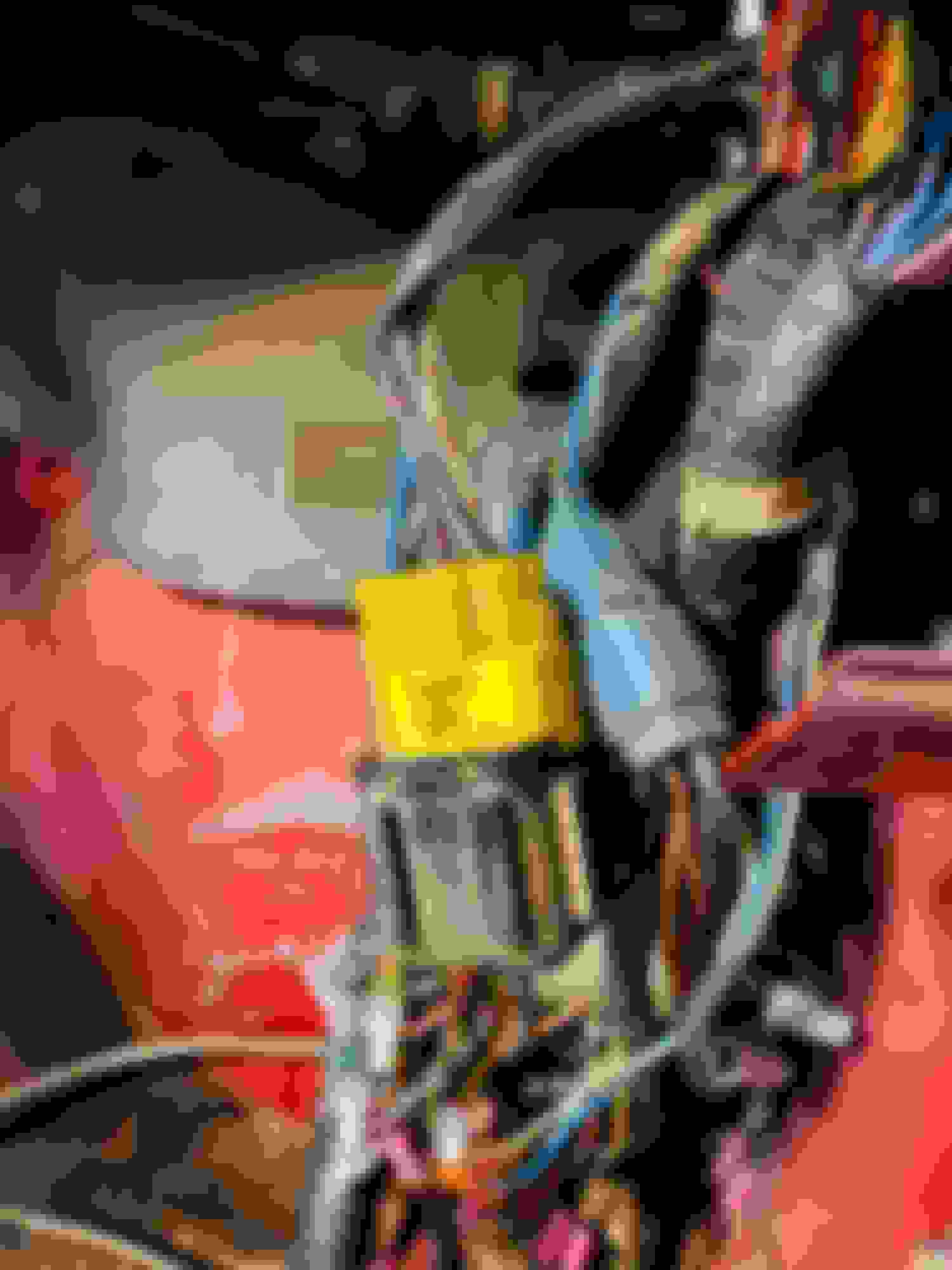
This is the circuit opening relay on the passenger side above the ECU. Continuity tested ok.
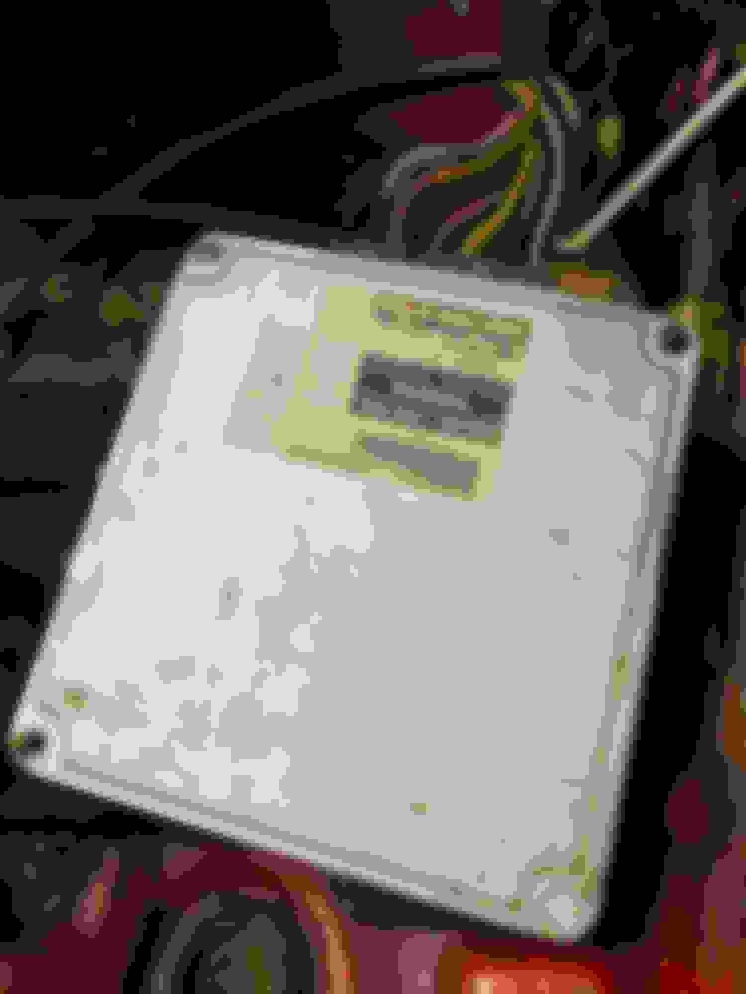
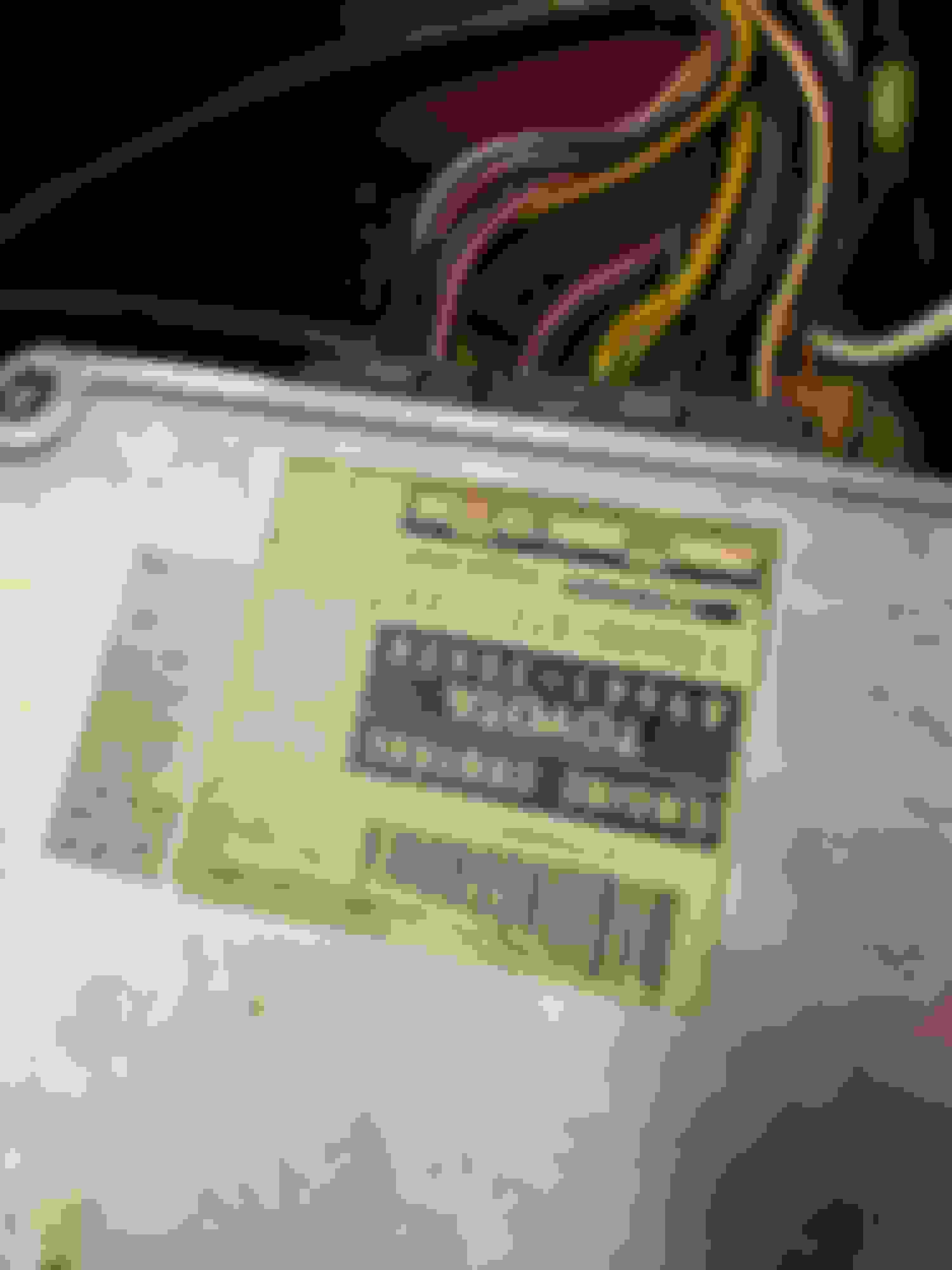
Here is the ECU. From parts shopping already sounds like I have a 22re from a 90'something vehicle.
And I'm still learning how to test all of this. Reading some other posts to make sure I am doing it right. Thanks again and hoping to track it down this afternoon.
Originally Posted by RAD4Runner
There is a crimp somewhere in loom under the intake manifold connecting ALL 4 injector negatives AND ECU pins 10 and 20 together. That could have been corroded/ broken when harness was moved. You can:
1) Inspect. and/or
2) Electrically test. IN order to reliably test electrically you need to access/disconnect injector connectors AND ECU connector then start probing for voltage/resistance.
Pin 2 of injectors always have 12V when IGN is on.
ECU pulses ground to #10 and #20 to turn on injectors.
T
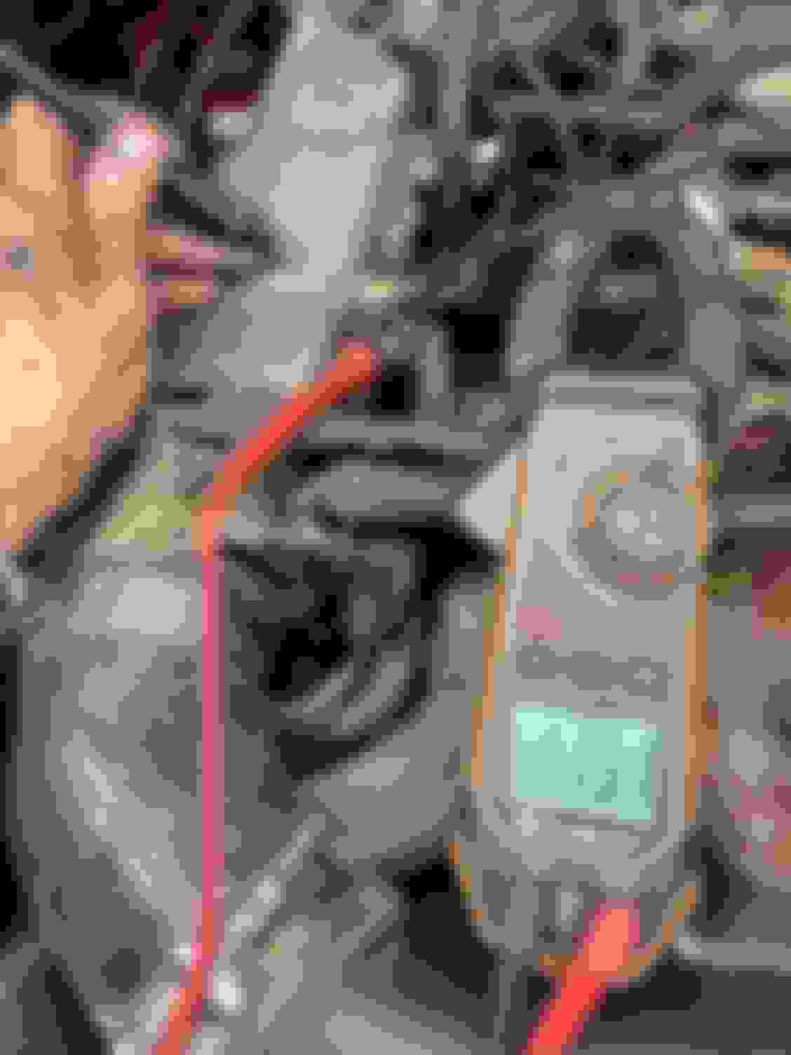
Tested the two injector connectors in the middle with the key in the on position. I have 10.9 volts on both sides of the connector when touched to the engine block... but nothing when checking voltage from one connector to the other.
That voltage is a bit low. Is the battery reading the same terminal to terminal? If it's higher, like 12 VDC or higher, you may have a bad ground connection from the battery to the metal of the body. Possibly a buildup of corrosion, either on the battery terminal(s), or on the actual connection the ground wire(s) have with the body metal.
The cables that actually attach to the battery terminals may have corrosion down inside the insulation, causing increased resistance of the wires. It can be pretty much invisible. Best way to check it is to ohm the cable, end to end, and flex it where there's insulation, to see if there's any change in the ohm value of the cable.
Make sure to clean the terminals of the battery, and the parts that attach to them. It doesn't take very much corrosion to have a major effect. The COR may not energize with only 10 VDC applied.
I cleaned both of these ground connections well and made sure they had solid connection with ground to bare metal. I get 12.26 across the battery terminals now. From the positive to the engine itself and then to the body the same. Are there any other grounds I am missing?
I have 11.51v from terminals on one of the injectors to the motor... same to the negative battery terminal now.
Yes, an important one: The ground from the head to the body. It normally runs from one of the bolts on the rear lifting hook to the firewall right behind the head. There should also be a ground wire from the alternator up to the PS bracket. With the ground to the firewall, it provides a good ground for proper alternator operation.
You should have the same positive voltage throughout the entire system. Or very close. If it's less, you have either bad connections in the connectors leading to your test point, or a corroded/dirty ground where you have the ground probe of the meter. As you can see, it doesn't take much corrosion/dirt to raise the resistance in these circuits a lot, thus reducing the voltage your seeing.
I found the one from the rear lifting hook to the firewall and it has great connection. Same voltage there as across the battery terminals. I did not see where a ground from the alternator goes up to the PS bracket. There are two wires coming off of it - one set in a connector that off the back that goes up into the wiring harness on the driver side... and the one bolted to the top of the alternator that also goes up into the wiring harness. I didn't see anything grounded and didn't find a ground coming out of the wiring harness inside that side of the engine compartment... Granted mine did have the 3.0 prior to having the 22RE put in so the PS bracket is the original for the 3.0 motor.
I was getting steady voltage everywhere I could check in those areas and connectors (grounds, etc...) and through all the connectors except for the circuit opening relay...
I think I will have to unwrap that entire leg to see where its losing voltage inside. If anyone has any other ideas let me know... otherwise I'll plan on taking apart the harness and checking all the connections and wires there.
Ok, an update. I have taken apart a good bit of my wiring harness to identify the wires and see where they are all going. I still have odd voltages on the circuit opening relay.
There are 5 wires coming off the circuit opening relay.
Blue: Goes to the fuel pump...
This pulls 10.5v and the pump turns on...
Green: currently disconnected and dead ends (shows it goes to the air flow sensor in the manual I have)
Black: Grounded to a bolt now... used to be attached to a corner of the ECU?
White w/ black line and single red stripes around it: goes up into the engine compartment near the battery... This one is also connected to another wire that is white with a black stripe (but no red markings) and I am not sure where this one goes yet.
I am not sure if these should connect to the battery or just be grounded in the engine compartment... tried both ways and didn't make a difference? This is in the wiring harness that I moved the most.
Black with single red strips around it: Goes to the main ignition relay on the driver side.
This has LOW voltage. 8.5v for some reason. Will be digging into this more... Could the relay be bad, even though I hear it click when turning the ignition?
All wires have continuity and I have been labeling them as I go.
Check out the schematic Rad4Runner posted up above. It has a good pinout of what wire goes where, to/from the COR.
It looks like the PO did some peculiar mods to the COR wiring harness, from your pictures. You might check those crimps, the small white ones, all through the harness. A light tug on both wires going to the crimp might tell you important info. Sorry, I just don't trust those things. To my mind, solder, and heat shrink, is the only way to fly, although just why all those wires required reconnection (crimps) I don't know.
Anywho, all those little white crimps are possible locations for bad connection/corrosion. Worth checking out.
Could the relay be bad, even though I hear it click when turning the ignition?
Positively yes, it sure could. Just because the relay "clicks", it's entirely possible the contacts that move have a buildup of corrosion on them. Corrosion on the contacts means a voltage drop across them, as the current tries to push the trons through the gunk on the contacts. The worse the corrosion, the worse the voltage drop. 4 volts is a pretty bad loss of voltage across that relay.
The fuse in the circuit could have dirty contacts as well. More voltage dropped. Easy to check. Pull the fuse out and look at it. A pencil eraser will clean them quite well. Putting it in and back out of it's slot will help clean the female contacts inside the fuse block.
Grounded to a bolt now... used to be attached to a corner of the ECU?
As long as the bolt is clean, and screwed into body metal. CLEAN, shiney body metal.The ECU body was/should be grounded to body metal. If the wire went to that, but now goes to the body directly, no big deal. A good clean ground is a good ground. Electrically, it's the same point. Electrically, it's like stepping once to the right when standing on the earth. You're STILL standing pretty much where you were before. Does that make sense?
Green: currently disconnected and dead ends (shows it goes to the air flow sensor in the manual I have)
If it shows it should go to the air flow sensor, then that's the wire the holds half the relay on, used after the start half is no longer in use.
The COR has two halves. One half is energized when the key is in the "start" position. This allows the fuel pump to pressurize the fuel system to get the engine started.
Once the engine fires, and the key is released to the "on" position, the second half of the relay is energized by the ground felt through the switch in the air flow meter. Once the vane opens, even a little, there's a switch that is closed, allowing a ground to be felt at the "run" half of the relay. This holds the run half of the relay energized while there's air flowing through the system. IE: The engine is running.
If that's not connected, the run half of the COR won't ever energize, so the fuel pump will shut down once the key is released. Sound familiar? If the fuel pump is being forced on somehow, bypassing the COR/Air meter pair, it's a VERY dangerous situation. The COR is designed to shut the fuel pump off during a crash. If that can't happen, the fuel pump may keep running after a crash. If a line has broken open, and the pump still runs, it's pumping fuel out onto the truck/ground. Talk about a fire hazard!!
The PO definitely spliced things together. Last night I did find one loose ground connection that I solidified which helped voltage in some areas of the system. I’ll check the others.
I will check the fuse tonight when I get back from work. Sadly none of the auto stores have a new relay in stock at the moment. If I had more time I would follow the instructions I have seen to bypass it using a Chevy or Ford relay to replace it… just in case…
Interesting about the fuel pump. I expect that is bypassed that wire then because my fuel pump literally runs all the time. If I turn the key to the on position it runs all the time. Shouldn’t it turn off once it hits pressure? It hasn’t ever been a problem running… but I could see how in a wreck or a roll over that would be a bad thing.
And your rambling has been very helpful. Thank you. Sadly I’ve been trying to get things ready so I can go wheel at Rock Junction in Grand Junction, CO tomorrow morning… but I don’t think I will make it. Was hoping to run Billings Canyon but since I can’t get it started looks like I will have to miss the event this year anyway! And it worked flawlessly for the last 3 years until I moved the harness (sigh).
Originally Posted by 2ToyGuy
Check out the schematic Rad4Runner posted up above. It has a good pinout of what wire goes where, to/from the COR.
It looks like the PO did some peculiar mods to the COR wiring harness, from your pictures. You might check those crimps, the small white ones, all through the harness. A light tug on both wires going to the crimp might tell you important info. Sorry, I just don't trust those things. To my mind, solder, and heat shrink, is the only way to fly, although just why all those wires required reconnection (crimps) I don't know.
Anywho, all those little white crimps are possible locations for bad connection/corrosion. Worth checking out.
Positively yes, it sure could. Just because the relay "clicks", it's entirely possible the contacts that move have a buildup of corrosion on them. Corrosion on the contacts means a voltage drop across them, as the current tries to push the trons through the gunk on the contacts. The worse the corrosion, the worse the voltage drop. 4 volts is a pretty bad loss of voltage across that relay.
The fuse in the circuit could have dirty contacts as well. More voltage dropped. Easy to check. Pull the fuse out and look at it. A pencil eraser will clean them quite well. Putting it in and back out of it's slot will help clean the female contacts inside the fuse block.
As long as the bolt is clean, and screwed into body metal. CLEAN, shiney body metal.The ECU body was/should be grounded to body metal. If the wire went to that, but now goes to the body directly, no big deal. A good clean ground is a good ground. Electrically, it's the same point. Electrically, it's like stepping once to the right when standing on the earth. You're STILL standing pretty much where you were before. Does that make sense?
If it shows it should go to the air flow sensor, then that's the wire the holds half the relay on, used after the start half is no longer in use.
The COR has two halves. One half is energized when the key is in the "start" position. This allows the fuel pump to pressurize the fuel system to get the engine started.
Once the engine fires, and the key is released to the "on" position, the second half of the relay is energized by the ground felt through the switch in the air flow meter. Once the vane opens, even a little, there's a switch that is closed, allowing a ground to be felt at the "run" half of the relay. This holds the run half of the relay energized while there's air flowing through the system. IE: The engine is running.
If that's not connected, the run half of the COR won't ever energize, so the fuel pump will shut down once the key is released. Sound familiar? If the fuel pump is being forced on somehow, bypassing the COR/Air meter pair, it's a VERY dangerous situation. The COR is designed to shut the fuel pump off during a crash. If that can't happen, the fuel pump may keep running after a crash. If a line has broken open, and the pump still runs, it's pumping fuel out onto the truck/ground. Talk about a fire hazard!!
Does all my rambling help at all?
Pat☺
Last edited by kwitcherbeliakin; 06-02-2022 at 11:41 AM.
kwitcherbeliakin,
Please do not use "black" font color on your text. They do not show on computer^^^. Use "automatic" instead.
Simple check if COR is working:
Put multimeter probe in Voltage mode on fuel pump power terminals.
Turn IGN on, Turn to "Start" / crank position. COR should click. You should get 12V at FP power terminals, AND FP should work if good and connected.
With IGN on, move flap of air flow meter open. COR should also click, and you get 12V at FP terminals, AND FP should work if good and connected. 1988 22R-E Schematic
sorry about the font. Was posting on my iPad yesterday and accidentally changed it. Couldn�t change it back.
ok so COR is the Circuit Opening Relay.
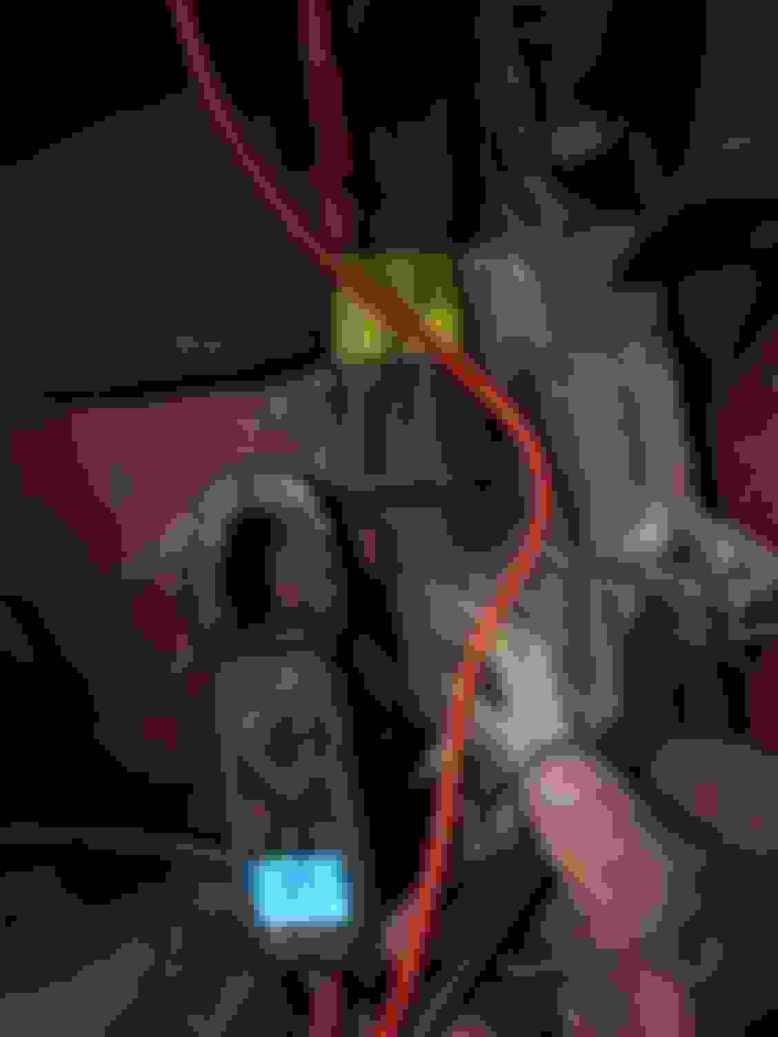
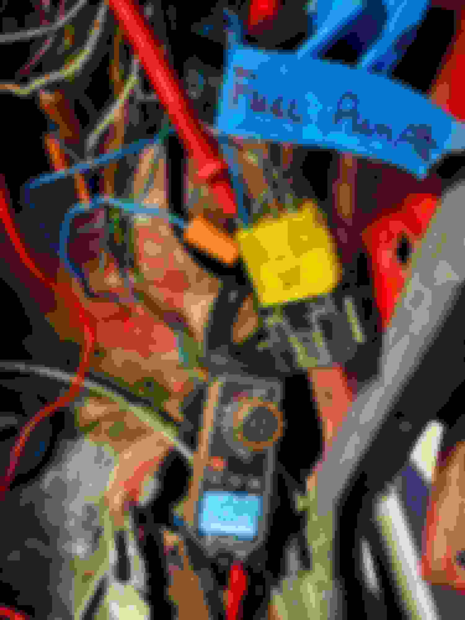
Below is a photo showing voltage at the FP terminal (blue wire w/ single red lines around it) with the ignition in the on position... the COR did not click but did provide power though only 10.89 volts... so there�s some loss.
we are 12.25v across the terminals right now.
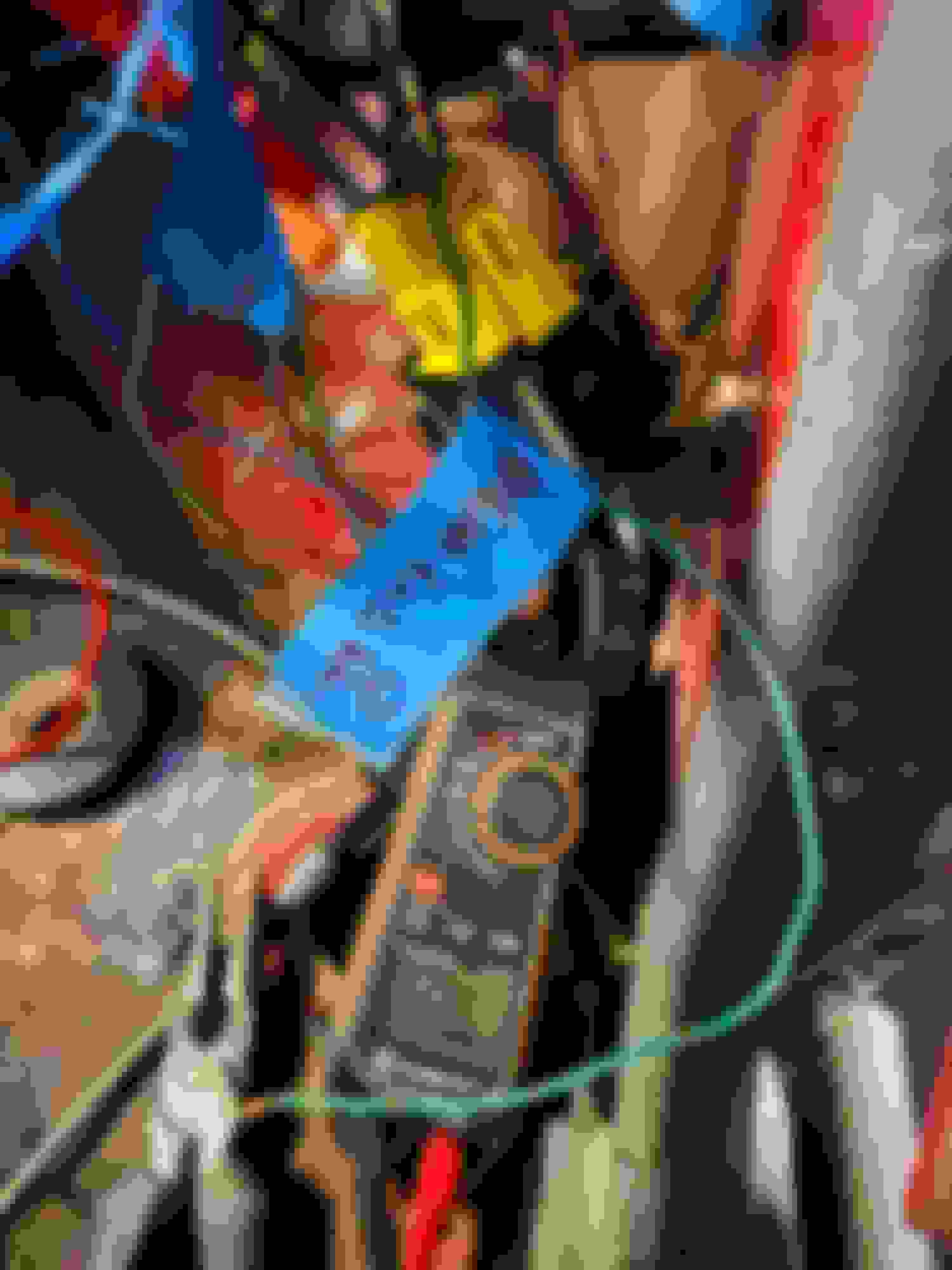
the green wire FC that goes to the Air Flow Semsor has never been hooked up in this rig. You did mention it provides the ground for the COR so with the ignition on I touched it to a ground and I did hear the relay click when that is touched. Voltage to FP stays the same. Photo below just shows the dead ended wire. Again it has never been hooked up and I haven�t had any issues starting till I moved wiring.
To give more of an update as I am trying to track this down today...
Given the lower voltage reading at the FP terminal I replaced the main EFI relay on the driver side hoping to increase voltage... which it did from my readings I posted previously. It reads 12.20v currently.
I replaced the two starter relays as one was corroded badly even though it was cranking fine... just not starting up. A previous owner installed these. They do have a 30 amp fuse between them and the battery. One flows into the other.
I disconnected 3 of the 4 injector connectors (minus the front one as I couldn�t get to it without removing something. I tested those and have voltage at the connectors with the key on. The voltage was a little higher than above as I had tested that first thing after charging it. I also tested voltage to the cold start injector with one tested on the negative battery terminal and the other inserted into the connector for the injectors.
I have reworked the wiring harness and redid all the connections that were here. This is a before and after. Once I get it started I will solder and heat shrink the connections.
connections aren�t beautiful but they are connected how I took them apart.
I have also tested for spark at the spark plugs with the front spark plug removed.
I am trying to trace down wires now to see where there might be a disconnect but it seams like the ECU isn�t telling the injectors to fire?
Both of the sensors on the front of the motor have also been replaced now.
Originally Posted by RAD4Runner
kwitcherbeliakin,
Please do not use "black" font color on your text. They do not show on computer^^^. Use "automatic" instead.
Simple check if COR is working:
Put multimeter probe in Voltage mode on fuel pump power terminals.
Turn IGN on, Turn to "Start" / crank position. COR should click. You should get 12V at FP power terminals, AND FP should work if good and connected.
With IGN on, move flap of air flow meter open. COR should also click, and you get 12V at FP terminals, AND FP should work if good and connected. 1988 22R-E Schematic
I don�t think this would have much to do with it not starting up at all but looks like I need at least one new wire from my distributor to my rear spark plug... the inside of it missing - component... first two are of the 2nd spark plug and wire connector boot up from the cab... and the next two are of the spark plug and boot closest to the cab...
the rear spark plug boot is missing the metal ring that grabs the spark plug... probably been that way since I got as I have nothing under the truck after disconnecting it...
I double checked to make sure fuel was freely flowing through a new fuel filter we put in awhile back.
Backed out the bolt to the cold start injector slightly and turned it to the on position for a moment. Gas pressurized and shot out.
Also loosened the bolt on the gas inlet downstream of the fuel filter on the bottom of the motor by the oil filter... fuel came out of there as well...
Also removed the drain line that sends it back down to the tank... that also shot fuel without issue... so I have fuel throughout the fuel rail.
so I have fuel... I have spark... has to be something on the connection between the ECU and the injectors... the ECU itself... or further down the line before the signal comes from the ECU.
I have continuity from the pins on the main harness to the three injectors I have unplugged...
Because I had continuity to all the injectors I checked then the bonded ground should be good?
What am I missing or what else should I check? What is the rest of the ignition sequence prior to that point?

 05-11-2022, 09:01 AM