
Help. 77 pickup gm ignitor swap
 09-15-2019, 03:18 PM
#1
Registered User
Thread Starter

Join Date: Sep 2019
Posts: 42
Likes: 0
Received 0 Likes
on
0 Posts
Help. 77 pickup gm ignitor swap
I bought a 77 toyota pickup with no spark. I figured it would be alot easier to do the GM module bypass. I noticed my distributor was the points style distributer so I found a distributer on CL from a 22r, it has 2 wires. Still no spark. I'm sure I have the ignition module and coil wired correctly. Red distributer wire to G, white to W, - side of coil to C, and B to the + side of coil and 12v. For 12v power im using the old (black w/ yellow strip) wire that went from the fuse box to the resistor and then to the old coil. I have tested it and I have 12v when the key is on.
The only possible problems I can see is that either I have a bad ground, but I tested the resistance from the module to negitive of battery and there is connection. Or the distributor I bought is bad.
How can I test the signal coming from the distributor? How can I test that my GM ignition module is good? How can I test my coil is good?how can I test that my coil is charging? Would it be ok to run the ground for the module directly to the battery.
Last edited by CMiller; 09-15-2019 at 03:24 PM.
 09-16-2019, 08:13 AM
#2
Registered User

I've done this conversion & do have a write-up on it on here. I'll take your questions in order.
Wiring - The Black with Yellow Stripe wire is the correct wire for power feed, but you mention it used to go to the resistor. You aren't using the old resistor in this new setup are you? If you are, remove the resistor from the circuit & connect/splice those 2 wires together. The HEI module needs full 12 volt power & the old ballast resistor will cut that down to something like 9 volts, & the module will not work, or work poorly. The ballast resistor is only there to save your old points from wearing out too fast. Now that you have eliminates the points, you don't need the resistor. And yes I do know that original & replacement ignition coils will have "FOR USE WITH EXTERNAL RESISTOR" printed on the coil body. Ignore it. You can run those coils at full 12 volt power & they will be fine. It's only printed on there because they expect that you are still running points. Good that you tested power with a meter, but if you have the resistor still in circuit & probed where the Black/Yellow wire goes into it, you're only reading battery power. If you measure after the resistor (what's coming out of it) you'll probably see less voltage than 12 volts. Ditch the resistor.
Did you measure power at the Module with the key in RUN position only? Did you also check to see if you had power at the Module while cranking (key START position)? Did you test for power on the Black/Yellow wire in BOTH the RUN and START positions?
Ground - A solid ground is critical to having the HEI Module work. The Module works by switching the Ground on & off to fire the coil. This runs from the Modules Ground Point, thru the switching transistor inside, then out to the coil via the C terminal. The correct grounding point on the Module is the eyelet hole closest to the B & C terminal side of the Module. it is on the right in this picture:
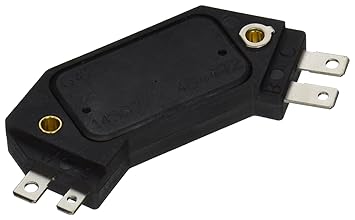
Note the larger eyelet with the little tab on it. I recommend a 14 gauge (or larger) ground wire with eye terminals of the correct size. I have 1 eye terminal under the head of the hold-down screw that goes into that right eyelet. I have the other end of the ground wire eye terminal between my fender (paint cleaned off to bare metal) & the mounting bracket for the voltage regulator, with the regulator mounting bolt holding it all down snug.
You may be reading resistance from Module to Battery Negative, showing a connection, but that connection may not be solid. It would be OK to run a ground from the Module direct to Battery Negative, but it's really not necessary. That's a long run of wire which could add resistance you don't need. You just need to run it to a solid body or frame ground (as previously described) somewhere near the Module's location. A good alternative location is the secondary ground wire that runs from the rear of the head to the firewall. This is basically a direct connection to Battery Ground, through the engine block & head. Make sure all connections are clean & tight,including your spade lug terminals on the Module tabs.
HEI Module Testing - Almost any auto parts store offers free testing (Auto Zone, O'Relley's, etc.) & they can check the module for you. What Brand & Part # of Module did you buy?
Ignition Coil -
The parts store can also test your ignition coil for free. If you have a Volt/Ohm Meter & know how to use it you can test it yourself. You measure the Primary & Secondary Resistances. Primary is measured on the + & - terminals. Secondary is measured on the + terminal & the Center Coil Output terminal. On the Primary reading, if you do not have a self-zeroing Ohm Meter, you need to connect your leads together 1st to find out what resistance is in your leads. You then subtract this from the reading you get on the + & - terminals to get the correct measurement.
The specs for your ignition coil should be:
Primary Resistance - 1.3 to 1.7 Ohms
Secondary Resistance - 6,500 to 10,500 Ohms
These are the stock Toyota specs for the ignition coil for '75 to '79, & the stock coil will work fine with the HEI Module. PLEASE NOTE - These specs are "cold specs". A faulty or failing ignition coil can still read good (within the specs) cold, but be out of spec once put to use & "heated up". If in doubt, just get a new quality ignition coil. I recommend the Standard UC12. DO NOT CHEAP OUT ON THE COIL! I have previously used a cheap coil & it didn't last 6 months, plus it wiped out the Module. The main cause of ignition module failure is a failed or failing ignition coil with too high a secondary resistance. Some of the windings inside can also break over time due to heat & vibration, in which case you have a broken circuit so no electricity will pass at all, so no spark.
Distributor - The main thing we need to look at is the Distributor Pickup Coil. This is a "trigger" for the Ignition Module. The 2 main factors are the coils resistance & the air gap setting between the Reluctor Ring ("spiked" ring inside) & the Coil's face. When one of the "spikes" passes the coil's face, it generates (induces) a low voltage signal, which is sent to the Ignition Module via the wires & triggers the Module. Average voltage on this action is usually less than 3 volts.
Pickup Coil Resistance - Spec is 140 to 180 Ohms. You can measure this with an Ohm Meter at the 2 leads coming from the distributor (Red & White wires). Disconnect the Red & White wires from the Ignition Module before taking a reading. If the reading is anything above 160 Ohms I'd say to replace the coil with a new one & set the airgap. That coil is also subject to aging & higher resistance from heat. Higher resistance can causes a loss of signal voltage & the Ignition Module won't trigger.
Pickup Coil Airgap - The spec for this is .004" to .012". If the gap is too big it won't generate a signal or the signal will be weak. Check the gap size with feeler gauges to find out what it is. Or if you don't have feeler gauges you can use a fairly new & crisp dollar bill to check it. The paper is .0043" thick, so just fold in half & stick it in the gap to check. I set mine up this way & it runs great. The folded bill yields .0086" so that's about perfect. Also easier than using a steel feeler gauge, because there is a magnet in the pickup coil that could cause you problems in getting an accurate check (steel gauge sticks to magnet).
Pickup Coil Signal Test - Disconnect Red & White wires from Ignition Module. Hook up your Volt/Ohm Meter set to 20 volt DC range. Crank engine over & watch the meter. You should get a pulsing reading of around 3 volts or more. Less than 3 volts and the airgap is out of adjustment or the coil is going or gone bad.
That's everything I can think of at the moment. Just go through everything in order step by step & you are likely to find the problem. Once setup correctly this system works like a charm on these engines. Let me know what you find out.
PS Are you sure you installed the replacement distributor correctly?
Wiring - The Black with Yellow Stripe wire is the correct wire for power feed, but you mention it used to go to the resistor. You aren't using the old resistor in this new setup are you? If you are, remove the resistor from the circuit & connect/splice those 2 wires together. The HEI module needs full 12 volt power & the old ballast resistor will cut that down to something like 9 volts, & the module will not work, or work poorly. The ballast resistor is only there to save your old points from wearing out too fast. Now that you have eliminates the points, you don't need the resistor. And yes I do know that original & replacement ignition coils will have "FOR USE WITH EXTERNAL RESISTOR" printed on the coil body. Ignore it. You can run those coils at full 12 volt power & they will be fine. It's only printed on there because they expect that you are still running points. Good that you tested power with a meter, but if you have the resistor still in circuit & probed where the Black/Yellow wire goes into it, you're only reading battery power. If you measure after the resistor (what's coming out of it) you'll probably see less voltage than 12 volts. Ditch the resistor.
Did you measure power at the Module with the key in RUN position only? Did you also check to see if you had power at the Module while cranking (key START position)? Did you test for power on the Black/Yellow wire in BOTH the RUN and START positions?
Ground - A solid ground is critical to having the HEI Module work. The Module works by switching the Ground on & off to fire the coil. This runs from the Modules Ground Point, thru the switching transistor inside, then out to the coil via the C terminal. The correct grounding point on the Module is the eyelet hole closest to the B & C terminal side of the Module. it is on the right in this picture:
Note the larger eyelet with the little tab on it. I recommend a 14 gauge (or larger) ground wire with eye terminals of the correct size. I have 1 eye terminal under the head of the hold-down screw that goes into that right eyelet. I have the other end of the ground wire eye terminal between my fender (paint cleaned off to bare metal) & the mounting bracket for the voltage regulator, with the regulator mounting bolt holding it all down snug.
You may be reading resistance from Module to Battery Negative, showing a connection, but that connection may not be solid. It would be OK to run a ground from the Module direct to Battery Negative, but it's really not necessary. That's a long run of wire which could add resistance you don't need. You just need to run it to a solid body or frame ground (as previously described) somewhere near the Module's location. A good alternative location is the secondary ground wire that runs from the rear of the head to the firewall. This is basically a direct connection to Battery Ground, through the engine block & head. Make sure all connections are clean & tight,including your spade lug terminals on the Module tabs.
HEI Module Testing - Almost any auto parts store offers free testing (Auto Zone, O'Relley's, etc.) & they can check the module for you. What Brand & Part # of Module did you buy?
Ignition Coil -
The parts store can also test your ignition coil for free. If you have a Volt/Ohm Meter & know how to use it you can test it yourself. You measure the Primary & Secondary Resistances. Primary is measured on the + & - terminals. Secondary is measured on the + terminal & the Center Coil Output terminal. On the Primary reading, if you do not have a self-zeroing Ohm Meter, you need to connect your leads together 1st to find out what resistance is in your leads. You then subtract this from the reading you get on the + & - terminals to get the correct measurement.
The specs for your ignition coil should be:
Primary Resistance - 1.3 to 1.7 Ohms
Secondary Resistance - 6,500 to 10,500 Ohms
These are the stock Toyota specs for the ignition coil for '75 to '79, & the stock coil will work fine with the HEI Module. PLEASE NOTE - These specs are "cold specs". A faulty or failing ignition coil can still read good (within the specs) cold, but be out of spec once put to use & "heated up". If in doubt, just get a new quality ignition coil. I recommend the Standard UC12. DO NOT CHEAP OUT ON THE COIL! I have previously used a cheap coil & it didn't last 6 months, plus it wiped out the Module. The main cause of ignition module failure is a failed or failing ignition coil with too high a secondary resistance. Some of the windings inside can also break over time due to heat & vibration, in which case you have a broken circuit so no electricity will pass at all, so no spark.
Distributor - The main thing we need to look at is the Distributor Pickup Coil. This is a "trigger" for the Ignition Module. The 2 main factors are the coils resistance & the air gap setting between the Reluctor Ring ("spiked" ring inside) & the Coil's face. When one of the "spikes" passes the coil's face, it generates (induces) a low voltage signal, which is sent to the Ignition Module via the wires & triggers the Module. Average voltage on this action is usually less than 3 volts.
Pickup Coil Resistance - Spec is 140 to 180 Ohms. You can measure this with an Ohm Meter at the 2 leads coming from the distributor (Red & White wires). Disconnect the Red & White wires from the Ignition Module before taking a reading. If the reading is anything above 160 Ohms I'd say to replace the coil with a new one & set the airgap. That coil is also subject to aging & higher resistance from heat. Higher resistance can causes a loss of signal voltage & the Ignition Module won't trigger.
Pickup Coil Airgap - The spec for this is .004" to .012". If the gap is too big it won't generate a signal or the signal will be weak. Check the gap size with feeler gauges to find out what it is. Or if you don't have feeler gauges you can use a fairly new & crisp dollar bill to check it. The paper is .0043" thick, so just fold in half & stick it in the gap to check. I set mine up this way & it runs great. The folded bill yields .0086" so that's about perfect. Also easier than using a steel feeler gauge, because there is a magnet in the pickup coil that could cause you problems in getting an accurate check (steel gauge sticks to magnet).
Pickup Coil Signal Test - Disconnect Red & White wires from Ignition Module. Hook up your Volt/Ohm Meter set to 20 volt DC range. Crank engine over & watch the meter. You should get a pulsing reading of around 3 volts or more. Less than 3 volts and the airgap is out of adjustment or the coil is going or gone bad.
That's everything I can think of at the moment. Just go through everything in order step by step & you are likely to find the problem. Once setup correctly this system works like a charm on these engines. Let me know what you find out.
PS Are you sure you installed the replacement distributor correctly?
09-16-2019, 07:56 PM
#3
Registered User
Thread Starter
Join Date: Sep 2019
Posts: 42
Likes: 0
Received 0 Likes
on
0 Posts
Update: I tested the pickup coil and it is bad. So there we go. But I also tested the voltage coming to the module and I have 12v with key in on position and when I crank it it drops to 10v. Probably just because the starter is running and then will return to 12v when the engine starts right? I tested the power to the coil by putting one probe on the the b terminal of the module and the other probe to ground. This is correct? My module is a napa brand, I can get the pn tomorrow. My module is grounded with a screw in the right hole. Im not using the resistor either. I noticed that the fuse in the fuse box for my ignition power wire has a 30 amp fuse but in the diagram i see has a 15 amp fuse, which is correct.
Last edited by CMiller; 09-16-2019 at 07:57 PM.
09-17-2019, 06:18 AM
#4
Registered User
What's the condition of your battery? A good battery should have at least 12.6 volts at rest (engine off & not charging). Yes, voltage will drop when cranking as the starter motor takes a decent amount of power to operate. Once the engine starts you should be reading charging voltage of 13.7 to 14.7 volts. Your test for power to the coil is not correct. What you describe is testing for power at the B terminal on the Module, because that is where you are probing. You have to actually probe the coil (+ terminal) to test for power to the coil. Does this make sense? Doing it the way you describe "skips over" the wire connection from the Module's B terminal to the + terminal on the coil. Any connection between two points may or may not have a problem. You have to check every link in the electrical chain when testing/troubleshooting.
The NAPA Brand ignition modules are good but overpriced. NAPA has them made for them by Standard Motor Parts, and the same part with the Standard brand name on it is usually half the price. I'm guessing that you have the NAPA/Echlin #ECH TP45. This is the same module as the Standard LX301.
You say the Module is "grounded with a screw in the right hole". Right as in correct? Or right vs left? This isn't clear. You didn't mention if you ran the ground wire I described? Also, did you get a heatsink for the module or no? It needs one. Change out that 30 amp fuse for a 15 amp. The "bigger" fuse could cause problems, like a fire, if you ever have a short in the ignition circuit.
10-06-2019, 06:46 AM
#6
Registered User
Great to hear. Good ground to the module is crucial to it working right. Original Stock spark plugs for the 20R are listed as:
NGK - BP5ES-L or
NipponDenso - W16EP
I am currently running the the Denso W16EXU plugs but any good quality plug should work for you. Here is a reference list for your '77:
https://www.rockauto.com/en/catalog/...park+plug,7212
Gap is .032", or 0.8mm.
NGK - BP5ES-L or
NipponDenso - W16EP
I am currently running the the Denso W16EXU plugs but any good quality plug should work for you. Here is a reference list for your '77:
https://www.rockauto.com/en/catalog/...park+plug,7212
Gap is .032", or 0.8mm.

Thread
Thread Starter
Forum
Replies
Last Post
Brown
95.5-2004 Tacomas & 96-2002 4Runners
78
03-02-2024 09:53 AM
Autophysn
84-85 Trucks & 4Runners
3
08-06-2013 09:11 PM
4bangercraig
86-95 Trucks & 4Runners
1
11-02-2012 04:39 PM


