Toyota Tundra: Why is My Power Window Not Working?
Learn why your windows may stop operating and how to address the issue.
This article applies to the Toyota Tundra (2000-present).
Car manufacturers build their vehicles with many "creature comforts" in mind. As automobiles progressed, they went from "hand crank" to "power buttons." It was a real luxury to be able to bring your window up or down at the push of a button. This is achieved via an electric module that operates through a series of wires, fuses and signals between the switch and the vehicle's on board computer or (ECU). With the introduction of electrical components, there comes an added layer of complexity or failure point. This is on top of a regulator or actuator, which is basically an internal motor that operates behind the door card to guide the glass up and down. Additionally, if there is a short in any of the wiring between this components, it could cause issues and will need repair/replacement.

Materials Needed
- Flat tip screwdriver
- Electrical probe
- Multimeter
- Electrical tape
- Wire splicers
- Electrical connectors
- Solder (optional)
- Toyota Service Manual
Step 1 – Check for continuity
There may be a break in constant DC voltage at a switch, fuse, module or wire.
If a switch, fuse or module is faulty, it will not read constant 12v voltage; same situation if there is a break in a wire between any of the systems.
- Turn the ignition to "ON" position.
- Use test light, probe or multimeter to test for 12v voltage at Driver's Control Module, which is located by foot well on driver's side.
- Use test light, probe or multimeter to test for 12v voltage at Driver's Window switch. The driver's window switch can be removed via flat tip screwdriver, so you can access the connector for testing.
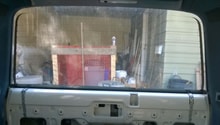
- Use test light, probe or multimeter to test for 12v voltage at Rear Power Window Module connector, which is located by driver's rear corner behind tail light.
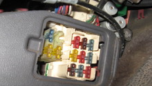
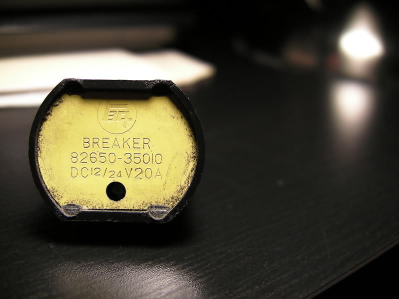
- Use test light, probe or multimeter to test for 12v voltage at circuit breaker. The circuit breaker is located far right of the driver's foot well near firewall.
- Use test light, probe or multimeter to check wiring between door to kick panel.
If it was found that one or more points in the system don't have continuous voltage, proceed to Step 2. If not, proceed to Step 3.
Step 2 – Repair/replace faulty fuse, module, relay or wire
The circuit is "broken" if one of the components in the system of window operations is broken or faulty.
The windows will all operate in a continuous circuit from each controlled module. If there is a short, a broken/missing module or blown fuse, the window(s) may not operate.
- Replace any blown fuses.
- Replace any faulty or missing modules and relays by disconnecting connector and screws and replacing unit as a whole.
- Repair wires that have shorts or breaks by using quality gauge wire, connectors and securing solid connections with electrical tape.
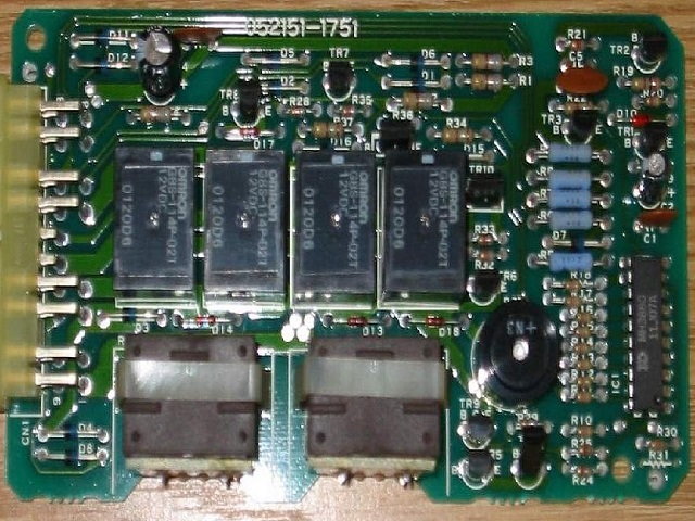
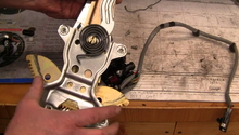
Figure 2. Inspect the board/controller for defects. 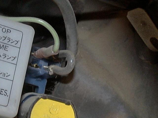
Figure 3. Inspect your connections.
Pro Tip
Spade connectors can be useful in using wires to jump relays. Some drop in relays can entirely replace relays used from the factory. It has also been noted that the rear power window shares a relay with the rear window wiper. This can be another point of failure to address/remedy.
If the result of this process still leaves some or all windows inoperable, proceed to Step 3.
Step 3 – Test or replace switch board
There is a switchboard behind the door cards that could be faulty.
The switchboard behind the door cards controls communication between window motor and switch along with the wiring to the kick panel.
- Use flat tip screwdriver to lift and disconnect the window switch.
- Use Allen wrench or screwdriver to remove door card.
- Remove door pin by unscrewing clockwise.
- Test continuity at switchboard.
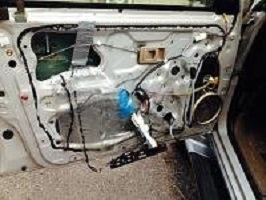
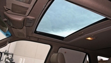
Figure 4. Door card removed. 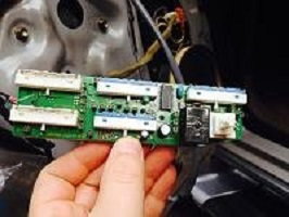
Figure 5. Board removed.
Pro Tip
You will want to make sure the switch itself is not faulty or not getting power before diving into this. As well as the wiring between the door and kick panel.
Step 4 – Reinstall components and switches
Once replacement or repair is done, put it all back together.
- Reconnect connectors.
- Reinstall switches.
- Reinstall relays and modules.
- Secure and reinstall door cards with screws.
- Reinstall door pins.
- Confirm windows are still working as expected
Related Discussions
- Locate Circuit Breaker - YotaTech.com
- Determining Why Power Windows Are Not Working - YotaTech.com
- Power Window Fuse Discussion - YotaTech.com
- Wiring Diagram PDF - YotaTech.com