Toyota 4Runner 1984-1995: How to Swap Gauge Cluster
The gauge cluster on your 1984 to 1995 4Runner is, well, rather unexciting. Now you have an option to install a picked SR5 cluster. It will spruce up your dashboard a bit and provide you with more information, too.
This article applies to the Toyota 4Runner (1984-1995).
Installing a SR5 gauge cluster in your dash will look great inside the cab. It will also give you more information because it replaces indicator lights with readable oil-pressure and battery-charging gauges. Removing the old one and installing the new one is simple, right? Not quite, as it can get a little complicated. This is mainly because you are changing from an oil-pressure indicator light to an oil gauge. We will walk you through the installation, including the sticky parts. Read on.
Materials Needed
- Salvaged or purchased SR5 gauge cluster
- New oil pressure sensor ($20)
- Phillips screwdriver (long shaft)
- Standard pliers
- Needle nose pliers
- Ratchet
- 1/16th-inch socket
- LED light bulbs (optional)
- Micro fiber cloth (optional)
Step 1 – Salvage or buy an SR5 gauge cluster
This initial step sounds simple, but first you need to determine which gauge cluster to salvage or buy. The difference is the speedometer: Is it cable-driven or electronic? There are two ways to determine this. The hard method is to open up the dashboard, pull out your current gauge cluster, and see if there's a cable attached in the back. The easy method is to check to see if there is a cable running from the firewall down to the transmission. The bottom line is if you see a cable connection, the cluster is cable-driven.
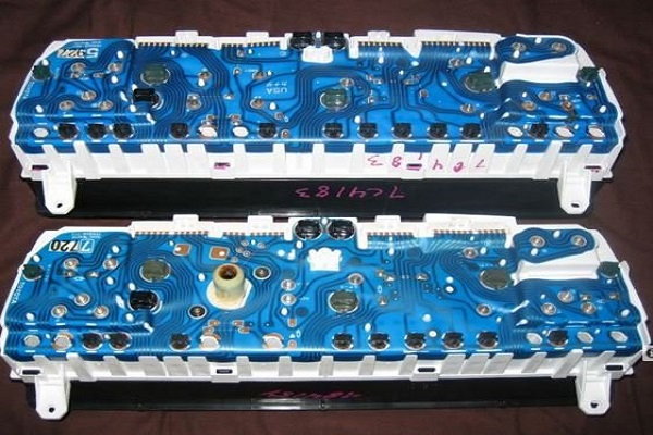
Figure 1. Back of gauge clusters: top is electric-driven speedometer and bottom is cable-driven speedometer. 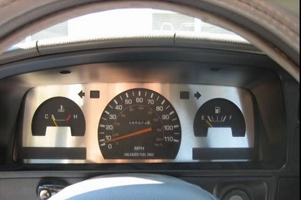
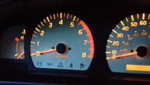
Figure 2. Example of old gauge cluster. 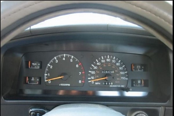
Figure 3. SR5 gauge cluster installed.
Pro Tip
Model year 1984 to 1991 SR5 pickups had cable-driven speedometers. After 1991, the speedometers are (mostly) electronic. Some owners report seeing cable-driven speedometers on SR5s after 1991. Use caution when selecting a gauge cluster based strictly on model and model year.
Step 2 – Disconnect the oil pressure sending unit
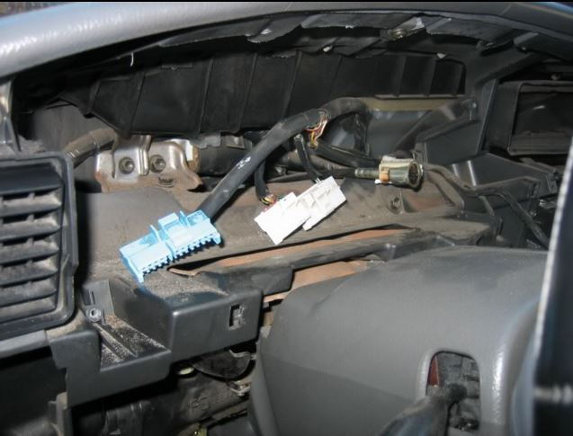
To avoid destroying the oil pressure gauge on the new cluster, reach into the passenger's side front fender and disconnect the oil pressure sending device.
A light on your current gauge cluster indicates insufficient oil pressure. The SR5 gauge cluster you will be installing has an actual oil gauge. The electronics that operate these two devices are different. The next step walks you through installing a modification to accommodate this difference.
Pro Tip
If you attempt to connect the oil pressure gauge without modifying the sensor, you will destroy the oil gauge.
Step 3 – Install new oil pressure sensor
You must replace this sensor so that the oil pressure gauge on the new cluster reports the oil pressure properly.
Buy a new oil pressure sensor from an auto parts store or online.
- Find the oil pressure sensor on the engine block near the oil filter.
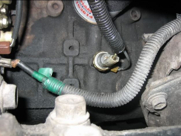
- Disconnect the electrical connection to the sensor.
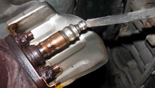
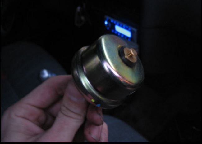
- Remove the rubber boot around the stock indicator-light sensor. Then use your ratchet and 1/16" socket to remove the stock sensor. Install the new oil pressure sensor.
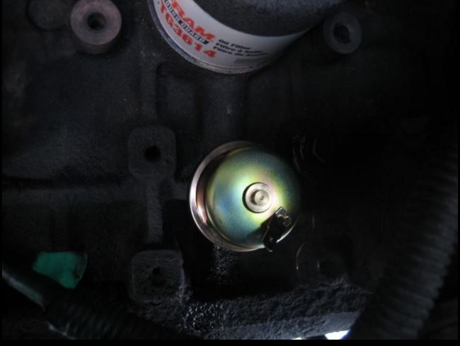
Figure 7. New oil pressure sensor installed.
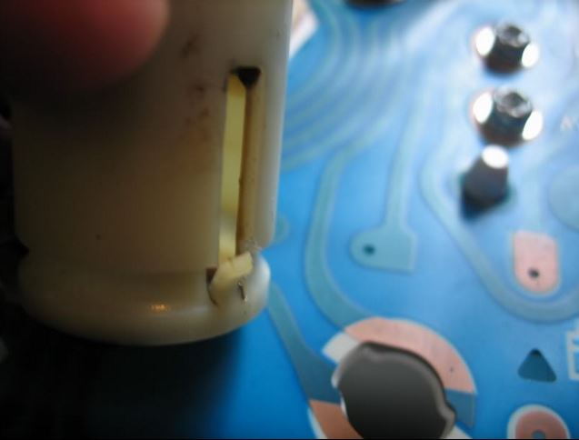
- The plug-in easily slides onto the new sensor's tab.
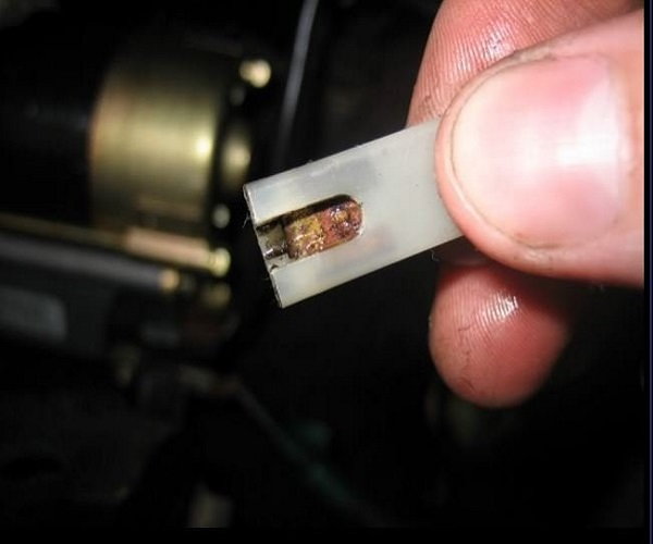
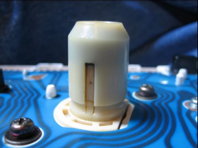
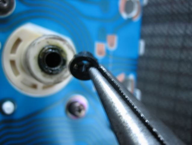
Figure 8. Plug. 
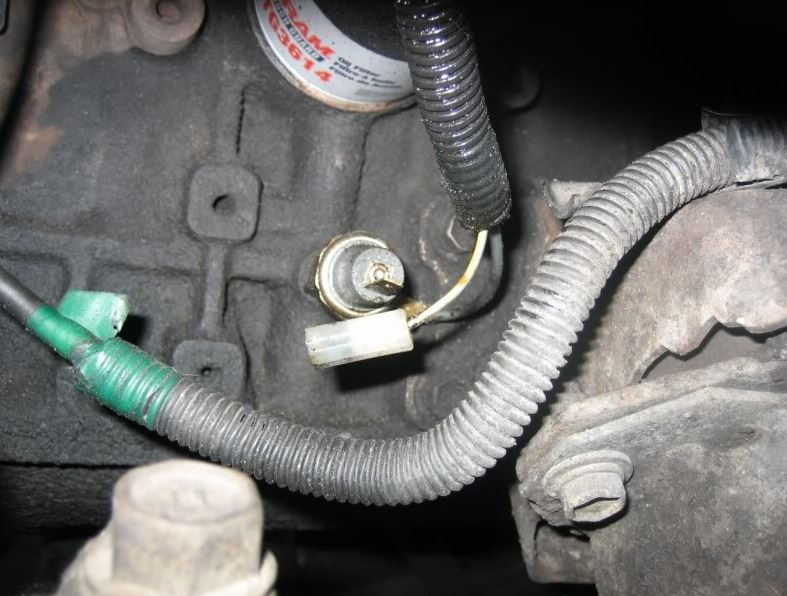
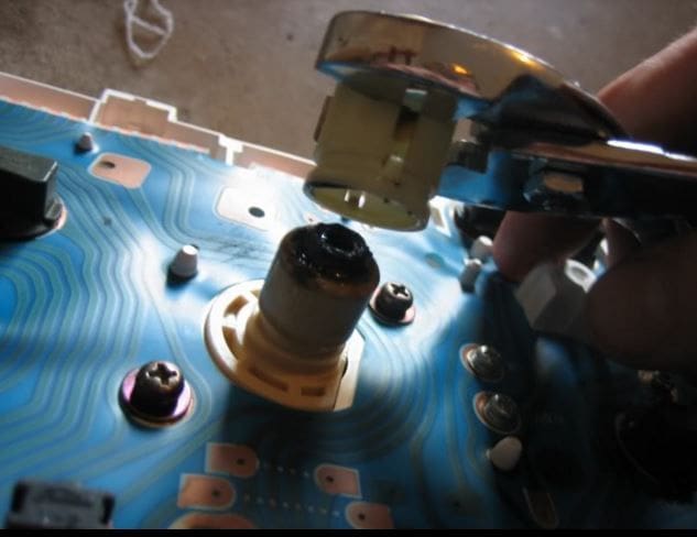
Figure 9. Plug installed. 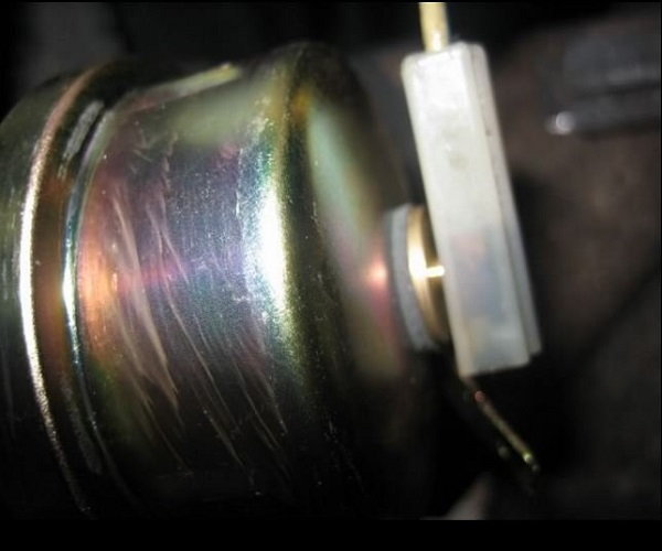
Figure 10. Close-up view of plug installed.
Step 4 – Remove the dash pieces
Before you can remove the old gauge cluster, you have to remove the following dashboard pieces.
- Remove the lower dash pieces, including the pieces below the gauge bezel and the passenger's side lower dash.
- Remove the glove compartment.
- Remove the center piece that surrounds the radio.
Step 5 – Remove the old gauge cluster
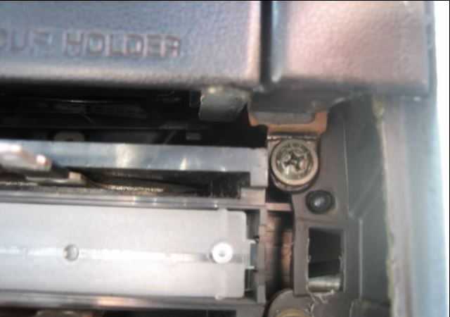
Find and remove the previously hidden screw to the right and under the cup holders. Use your Phillips screwdriver.
Use your Phillips screwdriver to remove the four screws around the gauge cluster. Pull the cluster out a little from the dashboard. You will see four plastic electronic connectors. If you have a cable-driven speedometer, you will also see a cable connection. Pull off the electronic connectors. If you have a cable connection, disconnect it by pushing down on the small tab on the cable itself and pulling the cable out.
Step 6 – Install new gauge cluster
Installing the new gauge cluster is the reverse of the removal.
- Put the new cluster in place.
- Connect the four electronic connections (also connect the cable if you have a cable-driven speedometer).
- Secure the cluster with the four screws.
- Reinstall the dash pieces, including the bezel around the gauge cluster, the center part the surrounds the radio, and the driver's as well as passenger's side lower dash pieces.
Pro Tip
As long as you have the gauge cluster apart, you may want to install new LED bulbs so you don't have to worry about bulbs burning out. Also, you may want to use the micro fiber cloth to clean the lens on the cluster before installing.
Step 7 – Cable-driven speedometers (special instructions)
The SR5 speedometer cable connection differs slightly from the connection of the standard cluster. The SR5 cluster has an adapter and a gasket that you must remove.
- To remove the adapter, first pry up the locking tabs that hold the adapter to the cluster.
- Push in the tabs and use your standard pliers to pull the adapter off.
- Use your needle nose pliers to remove the small black gasket.
- With all that done, your cable should fit.
Related Discussions
- Gauge Cluster Swap How-to - YotaTech.com
- SR5 Gauge Cluster Swap with Pictures - YotaTech.com
- SR5 Cluster for 4Runner - YotaTech.com
- Digital Cluster Swap - YotaTech.com
- Instrument Cluster Differences - YotaTech.com