92 3.0 HG diagnosis, questions (and replacement?) thread
 03-24-2011, 03:54 PM
#41
Registered User
x2 on replacing the knock sensor wire pig tail. It only costs about $11 from the dealer. The knock sensor itself is pretty sturdy, it is the wire that usually gets brittle and shorts out.
 03-24-2011, 07:09 PM
#44
Registered User
Thread Starter
Join Date: Feb 2008
Location: Dallas
Posts: 155
Likes: 0
Received 0 Likes
on
0 Posts
Okay, so here's the story on my ruined left HG. So I wanted to get the heads on the same way they came off. So I got it all set up:
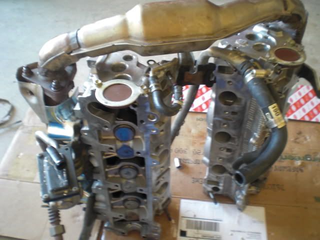
and went to drop it onto the block. Now, I knew that there was no way I bolted the crossover back on in the exact same spot as before, but there was some flex there so I thought I could get it onto the block okay. Well it didn't happen. So I decided to abort and in the process of pulling the heads back up the left side exhaust manifold got caught on the headgasket and bent it all out of shape. At least I can be glad I didn't spring for the pricey gaskets
So now I'm going to drop one head on with crossover attached. And then put the other one on after. Or I may just loosen the crossover bolts on one side so I have some play and try getting them both on at the same time again... not sure yet.
and went to drop it onto the block. Now, I knew that there was no way I bolted the crossover back on in the exact same spot as before, but there was some flex there so I thought I could get it onto the block okay. Well it didn't happen. So I decided to abort and in the process of pulling the heads back up the left side exhaust manifold got caught on the headgasket and bent it all out of shape.
At least I can be glad I didn't spring for the pricey gaskets So now I'm going to drop one head on with crossover attached. And then put the other one on after. Or I may just loosen the crossover bolts on one side so I have some play and try getting them both on at the same time again... not sure yet.
03-24-2011, 07:13 PM
#45
Registered User
Thread Starter
Join Date: Feb 2008
Location: Dallas
Posts: 155
Likes: 0
Received 0 Likes
on
0 Posts
When I got my heads back from the machinist I did notice this:
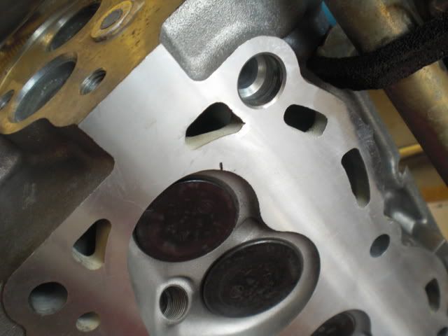
That is on the back left side cylinder (#6?) which is also where the HG died. Is this gonna make it fail again? I sure hope not... When I lay the gasket on the heads that little chip lays entirely within the cylinder opening of the gasket, but it still worries me a little. Has anyone else seen something like this?
That is on the back left side cylinder (#6?) which is also where the HG died. Is this gonna make it fail again? I sure hope not... When I lay the gasket on the heads that little chip lays entirely within the cylinder opening of the gasket, but it still worries me a little. Has anyone else seen something like this?
03-25-2011, 04:07 PM
#46
Registered User

Join Date: Mar 2011
Location: Botetourt, Va
Posts: 28
Likes: 0
Received 0 Likes
on
0 Posts
I had that same type mark on my head at #1, this is where mine had failed. It's just where the piston had made contact with the blown fire ring and made this mark, you'll be fine sense it doesn't protrude into the gasket or fire ring area.
P.S. Do the knock sensor wire, I'm sure it's brittle, you'll save yourself a headache.
P.S. Do the knock sensor wire, I'm sure it's brittle, you'll save yourself a headache.
03-25-2011, 05:32 PM
#47
Registered User
Thread Starter
Join Date: Feb 2008
Location: Dallas
Posts: 155
Likes: 0
Received 0 Likes
on
0 Posts
Thanks TiCain. I got the heads on today. What a PAIN! First I tried loosening the crossover on just the left side and dropping them both on at the same time. Didn't work. So then I detached the left head and put the right head with crossover attached on the block. Got some bolts on it to hold it in place. Then I tried to put the left head on but now the crossover was getting in the way So I had to loosen all the crossover bolts on the right head so I could get some wiggle on the crossover pipe. The left head then went on pretty easily and I got the crossover into position as well I ran out of time before I could get the heads and crossover torqued into position, but they are all sitting where they need to be.
Tomorrow I'm gonna start getting all the other pieces together. This will be the real test of how well I documented everything. I'm worried about a few bits and pieces, but hopefully it will go well.
I still need to find that Vacuum switching valve I broke and a wire for the knock sensor. Other than that most of my parts have been purchased!
Has anyone here done one of those home coolant flush deals? Any idea the best way to make sure that is all cleaned out? I'm not completely sure I'm gonna even flush the coolant system though, because it looks more like the antifreeze got into the oil than the other way around.
Next question: The water return tube that runs down the center of the block had a little o-ring type gasket where it attaches to the block. Should that have been included in my gasket kit? Cause mine looks pretty bad.
So I had to loosen all the crossover bolts on the right head so I could get some wiggle on the crossover pipe. The left head then went on pretty easily and I got the crossover into position as well I ran out of time before I could get the heads and crossover torqued into position, but they are all sitting where they need to be.Tomorrow I'm gonna start getting all the other pieces together. This will be the real test of how well I documented everything. I'm worried about a few bits and pieces, but hopefully it will go well.
I still need to find that Vacuum switching valve I broke and a wire for the knock sensor. Other than that most of my parts have been purchased!
Has anyone here done one of those home coolant flush deals? Any idea the best way to make sure that is all cleaned out? I'm not completely sure I'm gonna even flush the coolant system though, because it looks more like the antifreeze got into the oil than the other way around.
Next question: The water return tube that runs down the center of the block had a little o-ring type gasket where it attaches to the block. Should that have been included in my gasket kit? Cause mine looks pretty bad.
03-25-2011, 06:06 PM
#48
Registered User
Thread Starter
Join Date: Feb 2008
Location: Dallas
Posts: 155
Likes: 0
Received 0 Likes
on
0 Posts
Is p/n 82219A the knock sensor wire in this image?

finding replacement parts is tedious!
It's listed for $11 here:
http://www.toyotapartszone.com/Page_...reName=NE5469H
finding replacement parts is tedious!
It's listed for $11 here:
http://www.toyotapartszone.com/Page_...reName=NE5469H
03-26-2011, 03:43 AM
#49
Registered User
Join Date: Mar 2011
Location: Botetourt, Va
Posts: 28
Likes: 0
Received 0 Likes
on
0 Posts
Mine is a 94 3vze and even though there is a groove on the water bypass tube flange, it doesn't get an o-ring there, sealant fills that to make a better seal. I'd recommend Permatex " The right stuff " or go a little cheaper with Permatex gray if ya let it dry 24hrs before adding coolant, I used the gray with no problems.
P.S. The part # on my knock sensor pigtail was 82219-35010, fits 92-95 trucks and 4 runners, the 82219A is the same thing. Vacuum valve part # 90925-05047, that thing is around $50, might be able to find one in a salvage yard and save a few bucks.
P.S. The part # on my knock sensor pigtail was 82219-35010, fits 92-95 trucks and 4 runners, the 82219A is the same thing. Vacuum valve part # 90925-05047, that thing is around $50, might be able to find one in a salvage yard and save a few bucks.
Last edited by TiCain; 03-26-2011 at 05:24 AM.
 03-28-2011, 02:35 PM
#51
Registered User
Thread Starter
Join Date: Feb 2008
Location: Dallas
Posts: 155
Likes: 0
Received 0 Likes
on
0 Posts
A couple questions about this step from the FSM:
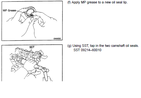
What exactly qualifies as MP grease? Also, do I need to tap that seal into place? Or can I just place the seal where it goes when I bolt the camshafts down?
What exactly qualifies as MP grease? Also, do I need to tap that seal into place? Or can I just place the seal where it goes when I bolt the camshafts down?
03-28-2011, 05:44 PM
#53
YotaTech Milestone-Two Millionth Post
if i'm not mistaken, those are alot like the front oil seal for the oil pump and i used MOLY lube ....just a smear...and a nice soft rap on a piece of wood on top of it drove it in straight.....i've imagined using a top from a detergent bottle to do the same....just not sure if it's the right diameter or if it's beefy enough to hold up to a hit of a hammer. again, i said i only "imagined" it.....i do that alot......i've disassembled and reassembled several times in my head
03-28-2011, 05:53 PM
#54
Registered User
 04-03-2011, 11:28 AM
#55
Registered User
Thread Starter
Join Date: Feb 2008
Location: Dallas
Posts: 155
Likes: 0
Received 0 Likes
on
0 Posts
Thanks for the pic wrenchinjoe.
So yesterday I was putting the head covers on. I got the Passenger side on okay and then went to put the D-side on and saw this:
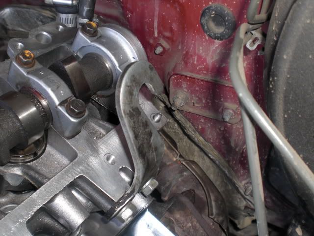
I remember when I pulled it apart thinking it was strange that I got 11 bolts from one side and 10 from the other. How did I not notice those threads sticking out during dissassembly? Or when I took the heads to the machine shop? Anyway, there is that broken bolt, so I got to figure out what to do with it. I haven't had a chance to see if I can get a good grip on it with some pliers and get it out yet. But that also means I need to track down a new bolt to go in that hole. Although it seemed to work fine without it before, but I'm sure it would start leaking oil there now if I did nothing with it.
So yesterday I was putting the head covers on. I got the Passenger side on okay and then went to put the D-side on and saw this:
I remember when I pulled it apart thinking it was strange that I got 11 bolts from one side and 10 from the other. How did I not notice those threads sticking out during dissassembly? Or when I took the heads to the machine shop? Anyway, there is that broken bolt, so I got to figure out what to do with it. I haven't had a chance to see if I can get a good grip on it with some pliers and get it out yet. But that also means I need to track down a new bolt to go in that hole. Although it seemed to work fine without it before, but I'm sure it would start leaking oil there now if I did nothing with it.
04-17-2011, 07:15 PM
#57
Registered User
Thread Starter
Join Date: Feb 2008
Location: Dallas
Posts: 155
Likes: 0
Received 0 Likes
on
0 Posts
So I got those extra threads out without too much trouble and got the valve covers on. Of course I forgot to put these on:
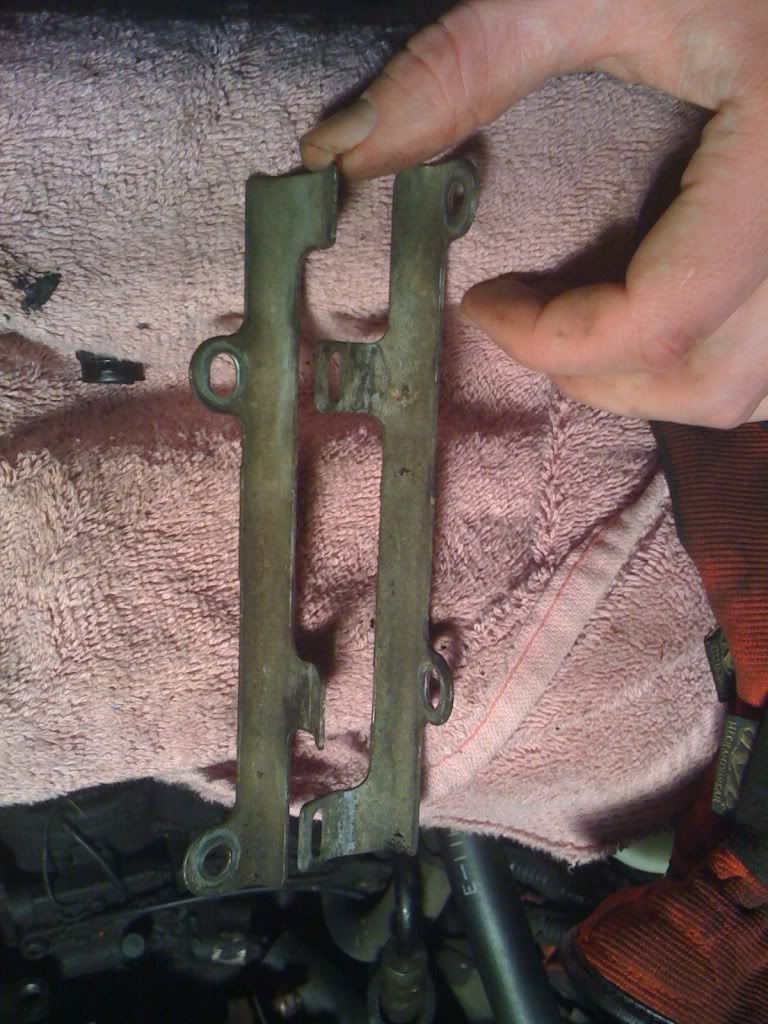
(pic compliments of redyota91's thread). Plus I can only find one of them. I know I put them together on the garage floor and now only one can be found. It might have something to do with my 3-yr old spending so much time in the garage with me while I'm working... I'll try to find another at the junkyard tomorrow along with a few other parts.
(pic compliments of redyota91's thread). Plus I can only find one of them. I know I put them together on the garage floor and now only one can be found. It might have something to do with my 3-yr old spending so much time in the garage with me while I'm working... I'll try to find another at the junkyard tomorrow along with a few other parts.
04-18-2011, 07:50 AM
#58
Registered User
I wouldn't worry about those harness brackets, both of mine disappeared after the dealer did HG's over a decade ago for the previous owner. I used some black flex tubing to give the wires a little protection when I put it all back together. Once the injectors are reconnected, the wiring harness doesn't move around much.
04-22-2011, 05:26 PM
#59
Registered User
Thread Starter
Join Date: Feb 2008
Location: Dallas
Posts: 155
Likes: 0
Received 0 Likes
on
0 Posts
Timing Belt Woes
Okay, so I'm trying to get the timing belt on and I am having some issues. First issue:
The FSM says to get both cam pulleys lined up with the arrow pointing straight up towards the mark on the timing belt cover no. 3. When doing this I noticed that as I turned them towards that mark they liked to snap past it. I suppose this is pressure from the valves on the cam lobes. After a few tries I got it to 'balance' at the right spot. Then, I got all the pulleys in place and the timing belt all lined up and installed. I turned the engine around 360 degrees and ended up with this:
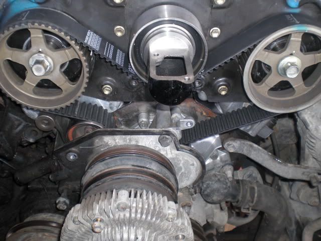
In case you can't tell from the pic the timing belt is one tooth off. Closer pics:
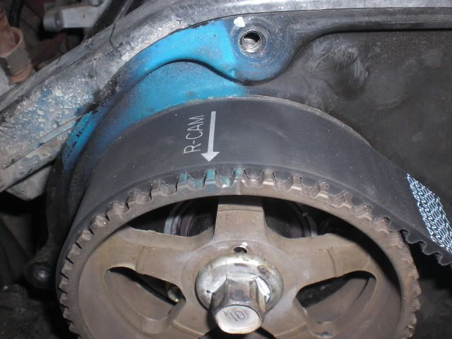
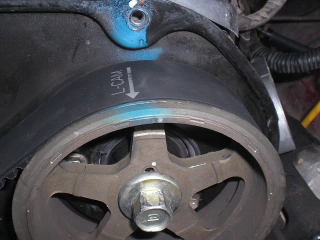
As you can see, it's not right . I'm sure it was lined up right before I spun it around, so what made it get off one tooth? I'm assuming that this is not okay.
Next question:
Where do I want that lined up? From looking at the FSM I would expect it to just be at 0 degrees, but I know I have heard people mentioning several different timing setups. What should I be shooting for?
A little help tonight before I try again tomorrow would be appreciated.
The FSM says to get both cam pulleys lined up with the arrow pointing straight up towards the mark on the timing belt cover no. 3. When doing this I noticed that as I turned them towards that mark they liked to snap past it. I suppose this is pressure from the valves on the cam lobes. After a few tries I got it to 'balance' at the right spot. Then, I got all the pulleys in place and the timing belt all lined up and installed. I turned the engine around 360 degrees and ended up with this:
In case you can't tell from the pic the timing belt is one tooth off. Closer pics:
As you can see, it's not right
. I'm sure it was lined up right before I spun it around, so what made it get off one tooth? I'm assuming that this is not okay.Next question:
Where do I want that lined up? From looking at the FSM I would expect it to just be at 0 degrees, but I know I have heard people mentioning several different timing setups. What should I be shooting for?
A little help tonight before I try again tomorrow would be appreciated.
04-22-2011, 06:37 PM
#60
Registered User
Don't worry about the marks on the timing belt itself, they help you line everything up for a first installation, but as soon as you rotate the engine the TB marks will not line up with the notches in the pulleys or timing covers any more.
From the pics it looks like your cam pulleys are lined up with the timing cover as they should be. The crankshaft pulley does apear to be off though.... Rotate the engine through a complete cycle (two full rotations of the CS) and stop turning the crank when the CS pulley lines up on 0*. Where your cam timing marks then? I think your cams are lined up with each other but may be a tooth out of sync with the CS.
If so, remove the tensioner and belt and line it up again. Start at the bottom with the crank lined up on 0*. Wrap the TB tightly up over the driver's side cam pulley first, and ensure that cam pulley mark lines up with the timing cover mark and that there is no slack in the belt. Then put a 17mm socket on the passenger side cam pulley and rotate it clockwise slightly (about 1 tooth). Wrap the TB under the idler pulley and then over the cam pulley and then using your 17mm socket rotate the cam pulley back counter clockwise and it will tension the belt. If you get that right, both cam pulleys will be lined up on the timing cover marks, the CS pulley with be on 0*, and the only slack in the belt will be along the side where the tensioner will take it up without moving the pulleys. Reinstall the tensioner, check to make sure nothing moved, rotate the CS two full rotations, stopping with the CS pulley on 0*. Hopefully your cam pulleys are sitting @ 12:00. If not, rinse and repeat.
Good luck, keep at it.
Last edited by Wrenchinjoe; 04-22-2011 at 07:38 PM.


